NIU2A-ES2 Manual
Edit this on GitLab
INTRODUCTION
This manual provides information about the North Atlantic Industries, Inc. (NAI) NIU2A System pre-configured and fitted with a Managed Ethernet Switch Function Module. The NIU2A-ES2 is a “Nano Interface Unit”; a small, rugged, low-power, self-contained, multifunction multi-port Managed Ethernet Switch with an integrated power supply that supports the NAI ES2 function module.
For a brief description of the unit and complete list of features, click here for the NIU2A data sheet.
CONVENTIONS USED IN THIS MANUAL

|
Note
|
An operating procedure, practice, or condition, etc., that is essential to emphasize. |
All numbers are expressed in decimal format unless otherwise noted.
Website
GENERAL SAFETY NOTICES
The following general safety notices supplement the specific warnings and cautions appearing elsewhere in the manual. They are recommended precautions that must be understood and applied during operation and maintenance of the instrument covered herein.
Death or serious injury may result if personnel fail to observe safety precautions. Dependent on configuration, some modules (e.g. Synchro / Resolver or AC signal sources) can generate output signals with high voltages. Be careful not to contact high-voltage connections when installing, operating, or maintaining this instrument.

The NIU2A-ES2 is delivered as a standalone system with no accessible or serviceable parts.
Repair
DO NOT ATTEMPT REPAIR. Under no circumstances should repair of this instrument be attempted. All repairs to this chassis must be accomplished at the factory.
High Voltage

HIGH VOLTAGE may be used in the operation of this equipment.
Input Power Always On

|
Note
|
The design of the model NIU2A-ES2 is such that DC input power is continuously supplied to internal circuits when connected to a main power source. To disconnect the NIU2A-ES2 from external power, the external power source should first be de-energized. The power input cable can then be disconnected. |
SYSTEM SPECIFICATIONS AND DETAILS
Introduction
The Nano Interface Unit multiport managed Ethernet Switch (NIU2A-ES2) is a second-generation, integrated, compact, “nano-sized” subsystem pre-configured and fitted with a managed multiport Ethernet switch. The NIU2A-ES2 connects to existing platform Ethernet networks, making data available to any system on the network.
The NIU2A-ES2 easily adds Ethernet-based sensor data acquisition and distribution and communication interfaces to mission computers without expensive chassis and backplane redesign. It has been designed with rugged embedded industrial, military and aerospace applications in mind.
Leveraging NAI’s field-proven, unique modular architecture, the NIU2A-ES2 supports connectivity to the NAI Configurable Open Systems Architecture (COSA™) which includes a wide selection of different Intelligent I/O, motion simulation/measurement and communications functions such as:
A/D Converter |
D/A Converter |
I/O TTL/CMOS |
RTD |
I/O Discrete |
I/O Differential Transceiver |
Synchro/Resolver LVDT/RVDT Measurement |
Synchro/Resolver LVDT/RVDT Simulation |
Strain Gage |
Encoder |
Dual-Channel Dual Redundant BC/RT/MT MIL-STD-1553 |
High-Speed Sync/Async RS232/422/423/485 |
ARINC 429/575 |
CANBus |
I/O Relay |
AC Reference |
Ethernet Switch |
SSD/Flash |
This approach provides unprecedented flexibility for supporting existing or new applications where there are specific interfacing requirements.
Significant application benefits include:
-
Independent (pre-processed) I/O functionality targeted to specific data acquisition/control areas
-
Additional capabilities, technology insertion and sensor interfacing to existing fielded applications
-
Minimal integration risk based on current field-proven, deployed technologies
-
Only ~ 7.2” x 2.7” x 3.0” @ ~2.7 lbs. (1.22 kg) conduction/convection cooled
-
16x Ethernet Switch Ports
-
10/100/1000Base-T (GbE) (default)
-
-
4x 10 Gb Fiber Optic 850 nm (optional)
SPECIFICATIONS
The NIU2A-ES2 is designed to meet the following general specifications.
General
Ethernet Data Transfer: |
Data transfers ~1 ms (typical) |
Input Voltage: |
18 to 36 VDC (28 VDC nominal) |
Power (Base unit): |
5 W @ 28 V VDC nominal plus module(s) power (see specific module(s) specifications). I/O Signal GND reference is isolated from main power source return and chassis. |
Power/Heat Dissipation: |
25 watts (maximum) when properly mounted to a cold-plate, which must be maintained at a temperature not to exceed 71°C. NOTE: The total NIU2A power dissipation is dependent on the configuration of the modules fitted in the NIU2A. |
Temperature, Operating: |
-40°C to 71°C (Conduction cooled: As measured at primary thermal transfer interface.) |
Temperature, Storage: |
-55°C to 105°C |
Size (approx): |
Depth: 3.0” (76.2 mm) |
Weight: |
The weight of an NIU2A system is dependent on the configuration. The approximate weight of the NIU2A is based on the selection of the functional module(s). The approximate weight of a typical configured NIU2A-ES2 is ~2.7 lbs. (1.22 kg). |
Environmental
Environmental MIL-STD-810 (1) (unless otherwise specified) |
||||||
No. |
Description |
Procedure |
Cycles |
Table |
Figure |
Comments |
514 |
Random Vibe |
Method 514.6, 0.1g2/Hz from 100 to 1K Hz., -3dB octave 5-100 Hz and -6dB 1K-2K Hz,(operational) |
||||
514 |
Sinusoidal Vibe |
TBD |
||||
501 |
Temp (High) |
3 |
3 periods (@ 4 hrs. ea.) within 24 hrs. cycle at 71 ºC baseplate |
|||
502 |
Temp (Low) |
1 |
3 periods (@ 4 hrs. ea.) within 24 hrs. cycle at -40 ºC baseplate |
|||
503 |
Temp (Shock) |
3 |
3 x 1 hr. each hot & cold cycle |
|||
507 |
Humidity |
II |
10 |
507.5-7 |
507.5-IX |
Cyclic high humidity (Cycle B2) |
500 |
Altitude (50K) |
II |
1 |
n/a |
n/a |
10m/s to 50,000ft for 1 hr. |
513 |
Acceleration |
II |
1 |
513.6-II |
n/a |
Carrier-based Aircraft (18g’s max) |
516 |
Shock - Operating |
I |
3 |
516.6-I |
n/a |
40g’s, 1 min each x 6 axis |
516 |
Shock - Crash |
V |
3 |
516.6-I |
n/a |
75g’s, 1 min each x 6 axis |
Ingress Protection IEC 60529 (1, 2) |
||||||
No. |
Description |
Procedure |
Cycles |
Table |
Figure |
Comments |
IP54 |
Dust Protection |
|||||
IP54 |
Water Splashing |
|||||
IP65 |
Dust Tight |
|||||
IP65 |
Water Jets |
|||||
EMI/EMC
EMC / MIL-STD-461 (1, 2*) |
||
MIL-STD-461(G) |
Method/Curve/Procedure |
Comments |
CE102 |
Conducted Emissions, Power Leads, 30 Hz - 10 kHz |
|
CS101 |
Conducted Susceptibility, Power Leads, 10 kHz - 10 MHz |
|
CS106 |
Conducted Susceptibility, Power Leads , 30 Hz - 150 kHz |
|
CS114 |
Conducted Susceptibility, Power Leads |
|
CS115 |
Conducted Susceptibility, Bulk Cable Injection, 10 kHz to 200 MHz |
|
CS116 |
Conducted Susceptibility, Bulk Cable Injection, Impulse Excitation |
|
RE101 |
Conducted susceptibility, Damped Sinusoidal Transients, Cables and Power Leads, 10 kHz to 100 MHz |
|
RE102 |
Radiated Emissions, Magnetic Field, 30 Hz to 100 kHz |
|
RS101 |
Radiated Emissions, Electric Field, 10 kHz to 18 GHz |
|
RS103 |
Radiated, Susceptibility, Magnetic Field, 30 Hz to 100 kHz |
|
Notes:
*1 - Designed to meet / Generic Test Reports Available
*2 - Utilizing proper shielded cables and system grounding practices
|
Note
|
Specifications are subject to change without notice. |
MTBF
Typical Mean Time Between Failures (MTBF) calculation estimates are as follows:
Product Root |
Part Number |
MTBF (hours) |
Temp (oC) |
Environment |
Model |
NIU2A |
NIU2A-2 |
889,678 |
25 |
GB |
*MIL-HDBK-217F N2 RELIABILITY PREDICTION + ANSI/VITA 51.0 & 51.1-2008 |
121,259 |
40 |
NS |
|||
82,910 |
45 |
GM |
|||
67,732 |
55 |
AIC |
|
Note
|
(*) MTBF Prediction calculations/estimates are provided for base unit only (the base unit is defined as the integrated motherboard, power supply unit (PSU) and interface connector assemblies and does not include any module(s)). |
Contact factory for other environment, temperature or configuration prediction calculation requests.
UNPACKING AND INSPECTION
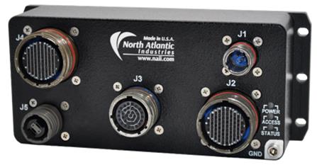
Figure 1. NIU2A-ES2
Unpacking
The NIU2A packing materials were designed specifically for transport protection of the NIU2A-ES2. When receiving the shipment container, inspect packaging for any evidence of physical damage. If damage is evident, it is recommended that the carrier agent is present when opening the shipping container. It is further recommended that all packing material is retained in the event the NIU2A-ES2 needs to be shipped elsewhere.
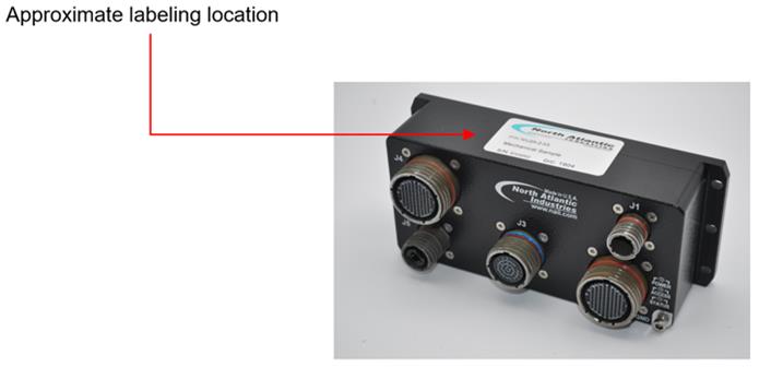
MECHANICAL INTERFACE
Mechanical Description
The NIU2A-ES2 is a rugged, aluminum, conduction-cooled system. It must be mounted to a cold plate. The system thermal management design considerations should ensure that the chassis thermal interface (NIU2A bottom surface) does not exceed 71°C. Mounting holes are provided on the chassis bottom housing flanges (as depicted). See the outline drawing below.
Mounting Requirements
Refer to NIU2A Outline and Installation Drawing (OID) or NIU2A with Fiber Outline and Installation Drawing (OID) for details on mounting and installing the NIU2A-ES2. It is available for download from NAI’s website. The NIU2A-ES2 is conduction cooled and must be mounted in accordance with the drawing. The OID provides recommended hardware, torque, cold-plate flatness and surface finish specifications, and thermal conductivity requirements.
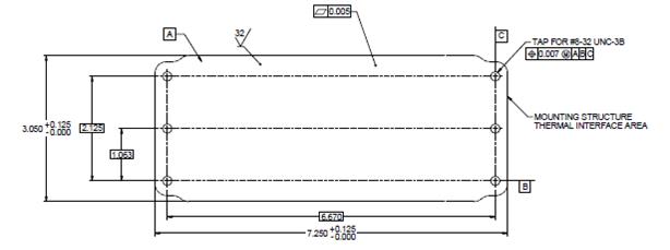
Figure 3. NIU2A Outline Dimensions/Cold Plate Mounting Pattern (Reference Only)
Notes:
-
For reference only (refer to the product web page for the latest revision NIU2A Outline and Installation Drawing (OID).
-
J5 Fiber optional Optic Connector is shown (connector is only populated when option is designated).
-
Unless otherwise specified, dimensions are in inches (mm); tolerances are:
-
2 PL DEC ±0.01; 3 PL DEC ±0.005
-
FRACT ±1/64 (0.4); ANGLES ±1/2 (12.7)
-
Chassis (Earth) GND
Chassis ground point threaded insert location is on the connector side of the NIU2A-ES2 as shown.

Figure 4. NIU2A-ES2 Outline Dimensions/Chassis GND location
|
Note
|
Chassis GND braid or equivalent to be secured by #6-32 screw/studs (with a depth of 0.3 inches) as end application requires. The NIU2A-ES2 chassis is provided with #6-32 threaded insert only. The recommended torque for the NIU2A-ES2 Chassis GND screw is 11 in-lbs. (125 N·cm) |
CONNECTOR DESIGNATIONS, LOCATIONS & DESCRIPTIONS
The Power, I/O Interface and Ethernet connectors are located on the NIU2A-ES2 front panel housing.
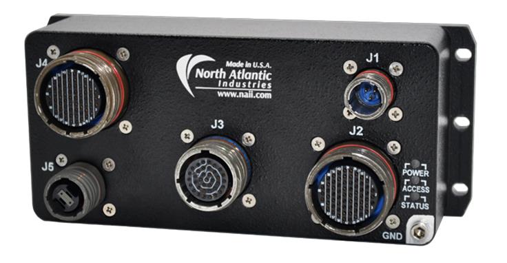
Figure 5. NIU2A-ES2 (Front Panel Connector Placement)
Connector Designation |
Description |
J1 |
Primary Power Connector, VDC |
J2 |
GbE Connector 1, Switch Ports 5-12 |
J3 |
1x GbE ES2 Module Maintenance Port, RS-232 Management & Debug Port, System Reset |
J4 |
GbE Connector 2, Switch Ports 1-4, 13-16 |
J5 |
4x Fiber Optic (optional configuration) |
Connector Details and Pinout
Generic pinout. See module I/O section or contact factory regarding any special module I/O configuration.
J1, Primary Power Connector
Primary input power is supported on the SIU36 via the J7 connector. Power input for the SIU36: 28 VDC (standard, default).

Figure 6. J1 Primary Power Connector Detail
Parts Identification
Chassis (Box-level) |
Mating Cable Connector |
||||
Designation |
MIL-DTL Equivalent Reference |
Shell/Insert |
Pin-count |
MIL-DTL Equivalent Reference |
NAI P/N (for reference) |
J1 |
D38999/20WA98PA (10,000 pF, incl. ‘c-filter') |
9 / 98 |
3 |
D38999/26WA98SA |
05-0297-COM |
J2, I/O, Module-1
The NIU2A-ES2 is pre-configured with the ES2 Ethernet Switch module. The J2 I/O connector supports eight of the sixteen Ethernet Switch ports (Ports 5 through 12).
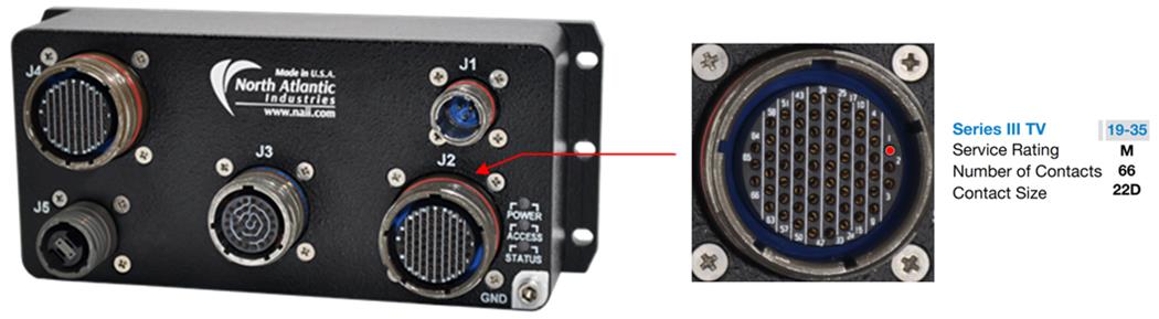
Figure 7. J2 I/O Module-1 Connector Detail
Parts Identification
Chassis (Box-level) |
Mating Cable Connector |
||||
Designation |
MIL-DTL Equivalent Reference |
Shell/Insert |
Pin-count |
MIL-DTL Equivalent Reference |
NAI P/N (for reference) |
J2 |
D38999/20WF35SN |
19 / 35 |
66 |
D38999/26WF35PN |
05-0284-COM |
Pinout
Generic pinout. See module I/O section or contact factory regarding any special module I/O configuration.
J2 Connector Pin |
Signal |
Notes |
J2 Connector Pin |
Signal |
Notes |
45 |
ETH05_T0N |
*1 |
46 |
ETH05_T0P |
*1 |
43 |
ETH05_T1N |
*1 |
44 |
ETH05_T1P |
*1 |
52 |
ETH05_T2N |
*1 |
53 |
ETH05_T2P |
*1 |
58 |
ETH05_T3N |
*1 |
51 |
ETH05_T3P |
*1 |
66 |
ETH06_T0N |
*1 |
65 |
ETH06_T0P |
*1 |
62 |
ETH06_T1N |
*1 |
63 |
ETH06_T1P |
*1 |
59 |
ETH06_T2N |
*1 |
64 |
ETH06_T2P |
*1 |
60 |
ETH06_T3N |
*1 |
61 |
ETH06_T3P |
*1 |
56 |
ETH07_T0N |
*1 |
57 |
ETH07_T0P |
*1 |
49 |
ETH07_T1N |
*1 |
50 |
ETH07_T1P |
*1 |
54 |
ETH07_T2N |
*1 |
55 |
ETH07_T2P |
*1 |
47 |
ETH07_T3N |
*1 |
48 |
ETH07_T3P |
*1 |
41 |
ETH08_T0N |
*1 |
42 |
ETH08_T0P |
*1 |
32 |
ETH08_T1N |
*1 |
33 |
ETH08_T1P |
*1 |
39 |
ETH08_T2N |
*1 |
40 |
ETH08_T2P |
*1 |
30 |
ETH08_T3N |
*1 |
31 |
ETH08_T3P |
*1 |
15 |
ETH09_T0N |
*1 |
16 |
ETH09_T0P |
*1 |
8 |
ETH09_T1N |
*1 |
9 |
ETH09_T1P |
*1 |
23 |
ETH09_T2N |
*1 |
24 |
ETH09_T2P |
*1 |
21 |
ETH09_T3N |
*1 |
22 |
ETH09_T3P |
*1 |
7 |
ETH10_T0N |
*1 |
3 |
ETH10_T0P |
*1 |
1 |
ETH10_T1N |
*1 |
2 |
ETH10_T1P |
*1 |
13 |
ETH10_T2N |
*1 |
14 |
ETH10_T2P |
*1 |
6 |
ETH10_T3N |
*1 |
12 |
ETH10_T3P |
*1 |
4 |
ETH11_T0N |
*1 |
5 |
ETH11_T0P |
*1 |
10 |
ETH11_T1N |
*1 |
11 |
ETH11_T1P |
*1 |
19 |
ETH11_T2N |
*1 |
20 |
ETH11_T2P |
*1 |
17 |
ETH11_T3N |
*1 |
18 |
ETH11_T3P |
*1 |
27 |
ETH12_T0N |
*1 |
28 |
ETH12_T0P |
*1 |
25 |
ETH12_T1N |
*1 |
26 |
ETH12_T1P |
*1 |
36 |
ETH12_T2N |
*1 |
37 |
ETH12_T2P |
*1 |
34 |
ETH12_T3N |
*1 |
35 |
ETH12_T3P |
*1 |
29 |
GND |
Signal/System Ground |
38 |
GND |
Signal/System Ground |
Notes
*1: 10/100/1000Base-T signal definitions:
ETHnn_Tx(y) where:
nn = Ethernet Switch Port number
x = Twisted pair/differential signal number
y = Differential signal polarity (p=positive(+) and n=negative(-))
J3, Ethernet Communication & Debug
The NIU2A-ES2 supports up to 16 10/100/1000Base-T switch ports and debug/maintenance signals. The ES2 switch port module debug/maintenance/configuration signals provided are a 10/100/1000Base-T maintenance port, RS-232 management & debug port and System Reset (for a soft reset/reload).

Figure 8. J3 Ethernet Communications & Debug Connector Detail
Parts Identification
Chassis (Box-level) |
Mating Cable Connector |
||||
Designation |
MIL-DTL Equivalent Reference |
Shell/Insert |
Pin-count |
MIL-DTL Equivalent Reference |
NAI P/N (for reference) |
J3 |
D38999/20WD35SN |
15 / 35 |
37 |
D38999/26WD35PN |
05-0302-COM |
Pinout
J3 Connector Pin |
Signal |
Signal |
Notes |
1 |
ETH-MAINT-TP2+ |
ETH2-TP2+ |
*4 |
2 |
ETH-MAINT-TP0+ |
ETH2-TP0+ |
*4 |
3 |
ETH-MAINT-TP1+ |
ETH2-TP1+ |
*4 |
4 |
ETH-MAINT-TP1- |
ETH2-TP1- |
*4 |
5 |
N/C |
ETH1-TP0+ |
*5 |
6 |
N/C |
ETH1-TP0- |
*5 |
7 |
N/C |
ETH1-TP3+ |
*5 |
8 |
N/C |
ETH1-TP3- |
*5 |
9 |
N/C |
ETH1-TP1+ |
*5 |
10 |
N/C |
ETH1-TP1- |
*5 |
11 |
N/C |
(+)5VUSB |
*5 |
12 |
N/C |
USB-GND |
*5 |
13 |
N/C |
USB-DM |
*5 |
14 |
N/C |
USB-DP |
*5 |
15 |
N/C |
RTC-STDBY |
*5 |
16 |
SER-GND |
SER-GND |
*2, *3 |
17 |
SER-TXD1 |
SER-RXD1 |
*2 |
18 |
SER-RXD1 |
SER-TXD1 |
*2 |
19 |
ETH-MAINT-TP2- |
ETH2-TP2- |
*4 |
20 |
ETH-MAINT-TP0- |
ETH2-TP0- |
*4 |
21 |
ETH-MAINT-TP3+ |
ETH2-TP3+ |
*4 |
22 |
ETH-MAINT-TP3- |
ETH2-TP3- |
*4 |
23 |
N/C |
ETH1-TP2+ |
*5 |
24 |
N/C |
ETH1-TP2- |
*5 |
25 |
GND |
GND |
*3 |
26 |
GND |
J1-26 |
*3 |
27 |
GND |
J1-27 |
*3 |
28 |
SYSRSTn |
SYSRSTn |
*1 |
29 |
N/C |
HDW_WP |
*5 |
30 |
GND |
GND |
*3 |
31 |
GND |
GND |
*3 |
32 |
GND |
GND |
*3 |
33 |
GND |
GND |
*3 |
34 |
GND |
J1-34 |
*3 |
35 |
GND |
J1-35 |
*3 |
36 |
GND |
J1-36 |
*3 |
37 |
GND |
GND |
*3 |
Notes
-
SYSRSTn : An active “low” or GND logic level (as referenced to System GND of the NIU3A) assertion of the SYSRST# signal (internally pulled ‘high') on the NIU3A processor and module cards will initiate an NIU3A system reset.
-
Debug: RS-232 Serial Communications Console port (Note: ES2 Switch Version SER-TX and SER-RX pinouts are reversed as compared with the NIU2A Generic reference pinouts. )
-
GND, SER-GND, USB-GND: All the identified GNDs are referenced to the same internal signal GND (System GND).
-
ETHx-TPyz: Standard NIU2A-ES2 configuration provides 1x 10/100/1000Base-T Ethernet ports.
-
(J3-xx): Signals are undefined in the standard NIU2A-ES2 configuration. These signals are considered no-connects (N/C).
J4, I/O, Module-2
The NIU2A-ES2 is pre-configured with the ES2 Ethernet Switch module. The J4 I/O connector supports eight of the sixteen Ethernet Switch ports (Ports 1 through 4 & 13 through 16).

Figure 9. J4 I/O Module-2 Connector Detail
Parts Identification
Chassis (Box-level) |
Mating Cable Connector |
||||
Designation |
MIL-DTL Equivalent Reference |
Shell/Insert |
Pin-count |
MIL-DTL Equivalent Reference |
NAI P/N (for reference) |
J3 |
D38999/20WF35SA |
19 / 35 |
66 |
D38999/26WF35PA |
05-0285-COM |
Pinout
Generic pinout. See module I/O section or contact factory regarding any special module I/O configuration.
J4 Connector Pin |
Signal |
Notes |
53 |
ETH01_T0N |
*1 |
45 |
ETH01_T0P |
*1 |
37 |
ETH01_T1N |
*1 |
28 |
ETH01_T1P |
*1 |
58 |
ETH01_T2N |
*1 |
51 |
ETH01_T2P |
*1 |
59 |
ETH01_T3N |
*1 |
52 |
ETH01_T3P |
*1 |
54 |
ETH02_T0N |
*1 |
46 |
ETH02_T0P |
*1 |
47 |
ETH02_T1N |
*1 |
38 |
ETH02_T1P |
*1 |
65 |
ETH02_T2N |
*1 |
64 |
ETH02_T2P |
*1 |
61 |
ETH02_T3N |
*1 |
60 |
ETH02_T3P |
*1 |
56 |
ETH03_T0N |
*1 |
55 |
ETH03_T0P |
*1 |
48 |
ETH03_T1N |
*1 |
39 |
ETH03_T1P |
*1 |
66 |
ETH03_T2N |
*1 |
62 |
ETH03_T2P |
*1 |
57 |
ETH03_T3N |
*1 |
63 |
ETH03_T3P |
*1 |
31 |
ETH04_T0N |
*1 |
40 |
ETH04_T0P |
*1 |
33 |
ETH04_T1N |
*1 |
32 |
ETH04_T1P |
*1 |
50 |
ETH04_T2N |
*1 |
49 |
ETH04_T2P |
*1 |
42 |
ETH04_T3N |
*1 |
41 |
ETH04_T3P |
*1 |
14 |
ETH13_T0N |
*1 |
13 |
ETH13_T0P |
*1 |
16 |
ETH13_T1N |
*1 |
15 |
ETH13_T1P |
*1 |
22 |
ETH13_T2N |
*1 |
21 |
ETH13_T2P |
*1 |
24 |
ETH13_T3N |
*1 |
23 |
ETH13_T3P |
*1 |
8 |
ETH14_T0N |
*1 |
9 |
ETH14_T0P |
*1 |
6 |
ETH14_T1N |
*1 |
7 |
ETH14_T1P |
*1 |
2 |
ETH14_T2N |
*1 |
3 |
ETH14_T2P |
*1 |
5 |
ETH14_T3N |
*1 |
1 |
ETH14_T3P |
*1 |
10 |
ETH15_T0N |
*1 |
4 |
ETH15_T0P |
*1 |
17 |
ETH15_T1N |
*1 |
18 |
ETH15_T1P |
*1 |
11 |
ETH15_T2N |
*1 |
12 |
ETH15_T2P |
*1 |
19 |
ETH15_T3N |
*1 |
20 |
ETH15_T3P |
*1 |
25 |
ETH16_T0N |
*1 |
26 |
ETH16_T0P |
*1 |
34 |
ETH16_T1N |
*1 |
35 |
ETH16_T1P |
*1 |
36 |
ETH16_T2N |
*1 |
27 |
ETH16_T2P |
*1 |
43 |
ETH16_T3N |
*1 |
44 |
ETH16_T3P |
*1 |
29 |
GND |
Signal/System Ground |
30 |
GND |
Signal/System Ground |
Notes
*1: 10/100/1000Base-T signal definitions:
ETHnn_Tx(y) where:
nn = Ethernet Switch Port number
x = Twisted pair/differential signal number (0, 1, 2, or 3)
y = Differential signal polarity (p=positive(+) and n=negative(-))
J5, Fiber Optic, Option
The NIU2A-ES2 supports up to four Tx and Rx Fiber Optic (Gb) Connections when appropriately configured.
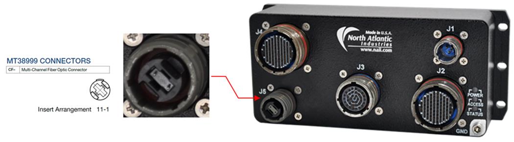
Figure 10. J5 Gb Fiber Optic Connector Detail (option)
Parts Identification
Chassis (Box-level) |
Mating Cable Connector |
||||
Designation |
(COTS) Equivalent Reference |
Shell/Insert |
Pin-count |
(COTS) Equivalent Reference |
NAI P/N (for reference) |
J5 |
MT38999 FO MIL-circular Amphenol: CF-599011-01S (Modified, NAI) Olive drab, Cd Includes: MT 12 fiber ferrule |
11/01 FO, single cavity |
N/A (FO ferrule) |
Amphenol: CF-599611-01P (olive drab, Cd) Includes: MT 12 fiber ferrule with female MT to 38999 adapter kit (MT female Assy Kit (flat ribbon) / Amphenol CF-198137-000) |
05-529 |
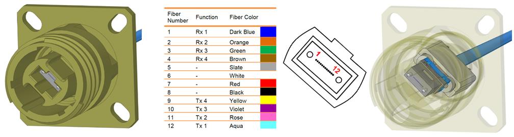
Figure 11. FO MT38999 Connector Fiber Ferrule Assembly Detail (for reference only)
POWER-UP & OPERATIONAL DESCRIPTION
Panel LEDs & Functions
Front Panel LEDs indications.
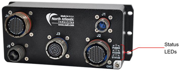
Figure 11. NIU2A-ES2 Status LEDs Location
LED |
STATUS / FUNCTION |
|
ILLUMINATED |
EXTINGUISHED |
|
POWER (GRN:) |
Blinking: Initializing |
Power-off |
ACCESS (YEL): |
Not Applicable (always extinguished) |
|
STATUS (RED): |
Not Applicable (always extinguished) |
|
ETHERNET WIRING CONVENTION
RJ-45 Pin |
T568A Color |
T568B Color |
10/100Base-T |
1000BASE-T |
NAI wiring convention |
1 |
white/green stripe |
white/orange stripe |
TX+ |
DA+ |
ETH-TP0+ |
2 |
green |
orange |
TX+ |
DA- |
ETH-TP0- |
3 |
white/orange stripe |
white/green stripe |
RX+ |
DB+ |
ETH-TP1+ |
4 |
blue |
blue |
DC+ |
ETH-TP2+ |
|
5 |
white/blue stripe |
white/blue stripe |
DC- |
ETH-TP2- |
|
6 |
orange |
green |
RX- |
DB- |
ETH-TP1- |
7 |
white/brown stripe |
white/brown stripe |
DD+ |
ETH-TP3+ |
|
8 |
brown |
brown |
DD- |
ETH-TP3- |
ES2 SWITCH CONFIGURATIONS & UTILITIES
Edit this on GitLab
Unless otherwise documented,
Default Configuration as shipped:
-
ES2 Port-1 is the only port which will be enabled. This allows GbE access for additional customer configuration or initialization after delivery. The RS-232 serial port is also available for console command configuration or initialization.
-
Switch IP Address: 12.0.0.1 / Subnet Mask: 255.0.0.0
The ES2 system supports different methods of accessing the switch, namely:
-
CLI (Command Line Interface using the serial port on the ES2)
-
Telnet, SSH (similar to CLI, but physical connection is an in-band Ethernet port)
-
HTTP (HyperText Transfer Protocol)
-
SNMP (Simple Network Management Protocol, which is an industry standard method of managing Ethernet networks)
Throughout this chapter, the management tool used is referenced as a standard Microsoft Windows-based “PC” running application software (e.g. terminal emulation or internet browser software).
Configuring the Management PC’s Ethernet Port
To allow each of the above-mentioned Ethernet configuration utilities to access the ES2, the PC’s Ethernet port must be configured properly. For example, if the ES2 default IP address was set to 12.0.0.1 with a subnet mask of 255.0.0.0, the management PC must be configured to operate within the same IP subnet.
Continuing with this example, the PC must now be configured to operate within this same IP subnet.
Set the IP address of the Network Interface Card on the PC to be within the same subnet. For example, set the PC’s IP address to be 12.0.0.20.
The various configuration utilities supported by ES2 allow the user to configure, manage, and monitor the ES2 switch. Overviews of the CLI, Telnet, SSH, HTTP, and SNMP methods of connecting to the Management Port are provided in this section of the manual.
Command Line Interface (CLI) Overview
Telnet/SSH Overview
Once the PC is configured to operate on the Management network, it is now possible to connect through the Ethernet port of the ES2 switch. To open a Telnet or SSH session, you can use applications such as Tera Term or simply a DOS Command window. Once the connection is established through this window, the Telnet or SSH session provides access to the CLI interface.
|
Note
|
The default ES2 login is root with password admin123. |
SNMP Overview
The Simple Network Management Protocol (SNMP) has proven to be a useful protocol for network management. Network administrators are well served by learning about SNMP and using this protocol to monitor and manage their networks. Although the SNMP standard is somewhat complex, entailing specific knowledge of MIB objects as well as requiring a large amount of configuration related to both SNMP agents and management software, the use of SNMP has been proven to be a cost-effective method of achieving a managed system.
There are many different software packages that can browse and manage MIB objects through the SNMP interface, and it is outside the scope of this manual to review them all.
Saving Configurations on Flash
Once the ES2 has been configured, it is possible to save the final configuration, and upon each subsequent reboot or power cycle the ES2 will initialize to this configuration.
These configuration settings may be saved though the Management Port interface and may be saved as many times as you choose.
Saving Configurations with CLI
Using the CLI interface, whether it is via the serial port or Telnet, the user must be logged on as administrator. As shown in “Telnet/SSH Overview", log in as username root and password admin123.
Assuming that the ES2 is completely configured and you would now like to save this configuration, from the command line type the following:
ES2# write startup-config
or
ES2# copy running-config startup-config
This utility saves the configuration onto the on-board Flash. Now every time the ES2 system is restarted, this base configuration will be re-invoked on the ES2.
To reset to factory defaults:
ES2# erase startup-config
Then power cycle the ES2 or reset the ES2 by typing the following:
ES2# reload
Command Line Interface
The CLI (Command Line Interface) is used to configure the ISS from a console attached to the serial port of the switch or from a remote terminal using TELNET or SSH.
The following table lists the generic CLI command modes.
Command Line Interface
Command Mode |
Access Method |
Prompt |
Exit method |
User EXEC |
This is the initial mode to start a session. |
es2> |
The logout method is used. |
Privileged EXEC |
The User EXEC mode command enable is used to enter the Privileged EXEC mode. |
es2# |
To return from the Privileged EXEC mode to User EXEC mode, the disable command is used. |
Global Configuration |
The Privileged EXEC mode command configure terminal is used to enter the Global Configuration mode |
es2(config)# |
To exit to the Privileged EXEC mode, the end command is used. |
Interface Configuration |
The Global Configuration mode command interface <interfacetype> <interfaceid> is used to enter the Interface configuration mode. |
es2(config-if)# |
To exit to the Global Configuration mode, the exit command is used and to exit to the Privileged EXEC mode, the end command is used. |
Config-VLAN |
The Global Configuration mode command vlan vlanid is used to enter the Config-VLAN mode |
es2(configvlan)# |
To exit to the Global Configuration mode, the exit command is used and to exit to the Privileged EXEC mode, the end command is used. |
Starting ISS
At the ISS login prompt that is displayed, use the user name root and password admin123 to access the CLI shell.
ISS login: root

Password: ********

es2#
Configuring the Switch
The basic configuration of the switch involves configuring IP address, VLAN, and so on. All commands and parameters can be abbreviated to their shortest unambiguous length. On the command line, the TAB key may be used to display available command options and autocomplete commands. The 'help' command displays a list of commands.
The ES2 comes up with a VLAN configured, by default. This VLAN is called the default VLAN (VLAN ID = 1). All ports in the switch are members of the default VLAN. Port 1 (g 0/3) is enabled by default.
The ports are configured and referenced as <interface-type>[space]<slot number>/<port number>
<interface-type> is either “gigabitethernet” or “extreme-ethernet” and can be abbreviated as “g” or “e”.
<slot number> is 0.
<port number> is 3 to 18 for 1 Gb ports and 1 to 4 for 10Gb ports.
| External port # | Internal nomenclature |
|---|---|
1 |
(g)igabitethernet 0/3 |
2 |
g 0/4 |
3 |
g 0/5 |
4 |
g 0/6 |
5 |
g 0/7 |
6 |
g 0/8 |
7 |
g 0/9 |
8 |
g 0/10 |
9 |
g 0/11 |
10 |
g 0/12 |
11 |
g 0/13 |
12 |
g 0/14 |
13 |
g 0/15 |
14 |
g 0/16 |
15 |
g 0/17 |
16 |
g 0/18 |
10 Gb fiber optic |
|
1 |
(e)xtreme-ethernet 0/1 |
2 |
e 0/2 |
3 |
e 0/3 |
4 |
e 0/4 |
Examples
The interfaces in the switch except for port 1 are disabled by default. Hence, enable all the interfaces that are to be used. This is done using the no shutdown command.
To enable all 16 gigabit ethernet ports
es2# c t
es2(config)# interface range g 0/3-18
es2(config-if-range)# no shutdown
es2(config-if-range)# exit
es2(config)# exit
es2#
To disable port 2
es2# c t
es2(config)# interf g 0/4
es2(config-if)# shutdown
es2(config-if)# end
es2#
To enable port 2
es2# c t
es2(config)# interf g 0/4
es2(config-if)# no shut
es2(config-if)# end
es2#
To enable all 4 10 Gb fiber ports
es2# c t
es2(config)# interf range e 0/1-4
es2(config-if-range)# no shut
es2(config-if-range)# end
es2#
To disable 10 Gb port 3:
es2# c t
es2(config)# interf e 0/3
es2(config-if-range)# shut
es2(config-if-range)# end
es2#
To enable 10 Gb port 3:
es2# c t
es2(config)# interf e 0/3
es2(config-if-range)# no shut
es2(config-if-range)# end
es2#
The show interfaces command displays the complete information of all available interfaces.
es2# show interfaces
A new VLAN can be configured using the following command. This command configures a new VLAN with VLAN ID 2.
es2(config)# vlan 2
Configure Port1, Port2, and Port3 as member ports. Port 1 is specified as an untagged port and Port 2 and Port 3 are set as tagged ports for VLAN 2.
es2(config-vlan)# ports gigabitethernet 0/1-3 untagged
gigabitethernet 0/1
es2(config-vlan)# exit
However, any untagged packets (packets sent from a PC/host) on any of the ports will be classified only to VLAN1. To ensure that untagged packets get classified onto a specific VLAN, it is required to change the port VLAN ID.
This is done using the following commands:
es2(config)# interface gigabitethernet 0/1
es2(config-if)# switchport pvid 2
es2(config-if)# exit
es2(config)# exit
Now untagged packets received on Port 1 will get classified to VLAN2. The ip address command can be used to configure the IP address of a VLAN interface.
es2# configure terminal
es2(config)# interface vlan 2
es2(config-if)# ip address 30.0.0.1 255.0.0.0
The interface status must be up for the IP interface to be reachable from an external host/PC.
es2(config-if)# no shutdown
es2(config-if)# exit
es2#
The show ip interface vlan <vlan-identifier> configuration can be used to check whether the configuration is successful or not.
es2# show ip interface vlan 2
Saving and Restoring Configuration
The configuration made by the user can be saved in the Flash and can be restored when the switch is started.
es2# write startup-config
The configurations saved using write startup config command will not update the configurations in issnvram.txt (that is, it will not change the factory default settings). If the factory default settings need to be changed, administrator should explicitly modify it through default ip address command.
Configuring the Default IP Address
Configuring the Default IP Address is a three-step procedure that will result in the IP address to be written to the NVRAM and configuration and this will be used as the IP address of the default interface when the switch is restarted.
-
Execute the default ip address command.
-
Configure the ip address for vlan 1.
-
Save the configuration.
Detailed Steps:
1) Execute the following commands to configure the Default IP Address.
Enter the Global Configuration mode.
es2# configure terminal
Configure the default IP address and subnet mask as 12.0.0.100 and 255.255.0.0, respectively.
es2(config)# default ip address 12.0.0.100 subnet-mask 255.255.0.0
Exit from the Global Configuration mode.
es2(config)# end
2) View the default IP address and subnet mask by executing the following command
es2# show nvram
Default IP Address : 12.0.0.1
Default Subnet Mask : 255.0.0.0
Default IP Address Config Mode : Manual
Default IP Address Allocation Protocol : DHCP
Switch Base MAC Address : 00:16:c6:ff:00:01
Default Interface Name : Gi0/3
Default RM Interface Name : NONE
Config Restore Option : Restore
Config Save Option : Startup save
Auto Save : Disable
Incremental Save : Disable
Roll Back : Enable
Config Save IP Address : 0.0.0.0
Config Save Filename : iss.conf
Config Restore Filename : iss.conf
PIM Mode : Sparse Mode
IGS Forwarding Mode : MAC based
Cli Serial Console : Yes
SNMP EngineID : 80.00.08.1c.04.46.53
Proceed to section “Configuring IP address for an Interface” and set the same IP address and subnet mask for VLAN 1 (default VLAN). The switch will have this IP address and subnet mask after the switch restart only if the allocation method is manual.
Setting the Default IP Allocation Mode for the Switch
Setting the default IP allocation mode for the Switch configures the mode by which the default interface acquires its IP address. The default IP allocation mode for a switch can be manual or dynamic. The default value is manual.
1) Execute the following commands to change the default IP allocation mode of the default VLAN.
Enter the Global Configuration mode.
es2# configure terminal
Configure the default mode to dynamic.
es2(config)# default mode dynamic
Exit from the Global Configuration mode.
es2(config)# end
2) View the default mode by executing the following command.
es2# show nvram
Default IP Address : 12.0.0.1
Default Subnet Mask : 255.0.0.0
Default IP Address Config Mode : Dynamic
Default IP Address Allocation Protocol : DHCP
Switch Base MAC Address : 00:01:02:03:04:01
Default Interface Name : Gi0/1
Config Restore Option : No restore
Config Save Option : No save
Auto Save : Enable
Incremental Save : Disable
Roll Back : Enable
Config Save IP Address : 0.0.0.0
Config Save Filename : iss.conf
Config Restore Filename : iss.conf
PIM Mode : Sparse Mode
IGS Forwarding Mode : MAC based
Cli Serial Console : Yes
SNMP EngineID : 80.00.08.1c.04.46.53
ISS uses the dynamic address allocation protocols - BOOTP or DHCP or RARP - to acquire the IP for management VLAN during switch restart.
Configuring Default IP Address Allocation Protocol
Configuring the default IP address allocation protocol configures the protocol by which the default interface dynamically acquires its IP address.
1) Execute the following commands to configure the default dynamic address allocation protocol.
Enter the Global Configuration mode.
es2# configure terminal
Configure the default allocation protocol.
es2(config)# default ip address allocation protocol dhcp
Exit from the Global Configuration mode.
es2(config)# end
2) View the default IP Address Allocation Protocol by executing the following command
es2# show nvram
Default IP Address : 12.0.0.100
Default Subnet Mask : 255.255.0.0
Default IP Address Config Mode : Dynamic
Default IP Address Allocation Protocol : DHCP
Switch Base MAC Address : 00:01:02:03:04:01
Default Interface Name : Gi0/1
Config Restore Option : No restore
Config Save Option : No save
Auto Save : Enable
Incremental Save : Disable
Roll Back : Enable
Config Save IP Address : 0.0.0.0
Config Save Filename : iss.conf
Config Restore Filename : iss.conf
PIM Mode : Sparse Mode
IGS Forwarding Mode : MAC based
Cli Serial Console : Yes
SNMP EngineID : 80.00.08.1c.04.46.53
Configuring IP Address for an Interface
Configuring IP address for an Interface configures the IP address which will be used for sending and receiving the packets.
1) Execute the following commands to configure an IP address for a VLAN interface. Enter the Global Configuration mode.
es2# configure terminal
Enter the Interface Configuration mode.
es2(config)# interface vlan 1
Shut down the VLAN interface.
es2(config-if)# shutdown
Configure the IP address and subnet mask.
es2(config-if)# ip address 12.0.0.100 255.0.0.0
Bring up the VLAN interface.
es2(config-if)# no shutdown
Exit from the Interface Configuration mode.
es2(config)# end
Configuring the IP address for an Interface requires the interface to be shutdown prior to the configuration.
2) View the configured interface IP address by executing the following show command.
es2# show ip interface
Vlan1 is up, line protocol is up
Internet Address is 12.0.0.100/8
Broadcast Address 10.255.255.255
3) Save the configuration
es2# wr st
Configuring an Interface to Acquire Dynamic IP
An interface can be configured to acquire the dynamic IP address either from DHCP or from RARP. The default value is DHCP.
1) Execute the following commands to acquire dynamic IP for VLAN 1 through DHCP.
Enter the Global Configuration mode.
es2# configure terminal
Enter the Interface Configuration mode.
es2(config)# interface vlan 1
Configure the VLAN interface to dynamically acquire an IP address through the Dynamic Host Configuration Protocol
es2(config-if)# ip address dhcp
Exit from configuration mode.
es2(config)# end
2) View the configured IP address by executing the following show command.
es2# show ip interface
Vlan1 is up, line protocol is up
Internet Address is 12.0.0.1/8
Broadcast Address 10.255.255.255
IP address allocation method is dynamic
IP address allocation protocol is dhcp
A DHCP server must exist in the network to allocate dynamic IP through DHCP mechanism.
Industry Standard CLI (Command Line Interface)
CLI commands are focused on performing specific operations. In order to provide a consistent, composable user experience, the CLI commands of the NIU2A-ES2 protocols and IP implementation solutions adhere to the Industry Standard CLI syntax.
The following table provide a listing and identification of which CLI commands are supported.
NAI Reference ONLY |
Package Details (NAI Reference ONLY) |
NAI |
|||||
CLI Volume No: |
Chapter No: |
Chapter Title |
Work Group |
Enterprise |
Metro |
Metro_E |
NIU2A-ES2 Support |
1 |
1 |
Introduction |
NA |
NA |
NA |
NA |
|
2 |
Command Line Interface |
NA |
NA |
NA |
NA |
||
3 |
System Commands |
Y |
Y |
Y |
Y |
YES |
|
4 |
System Features |
Y |
Y |
Y |
Y |
YES |
|
5 |
VCM |
N |
Y |
Y |
N |
YES |
|
6 |
RADIUS |
Y |
Y |
Y |
Y |
YES |
|
7 |
TACACS |
Y |
Y |
Y |
Y |
YES |
|
8 |
SSH |
Y |
Y |
Y |
Y |
YES |
|
9 |
SSL |
Y |
Y |
Y |
Y |
YES |
|
10 |
SNTP |
Y |
Y |
Y |
Y |
YES |
|
11 |
SNMPv3 |
Y |
Y |
Y |
Y |
YES |
|
12 |
Syslog |
Y |
Y |
Y |
Y |
YES |
|
13 |
TCP |
Y |
Y |
Y |
Y |
YES |
|
14 |
UDP |
Y |
Y |
Y |
N |
YES |
|
15 |
PoE |
Y |
Y |
Y |
N |
NO |
|
16 |
L2 DHCP Snooping |
Y |
Y |
Y |
Y |
NO |
|
17 |
IPDB |
Y |
Y |
Y |
Y |
YES |
|
2 |
18 |
STP |
Y |
Y |
Y |
Y |
YES |
19 |
LA |
Y |
Y |
Y |
Y |
YES |
|
20 |
LLDP |
Y |
Y |
Y |
Y |
YES |
|
21 |
PNAC |
Y |
Y |
Y |
Y |
YES |
|
22 |
MRP |
Y |
Y |
Y |
Y |
NO |
|
23 |
ELMI |
N |
N |
Y |
Y |
NO |
|
24 |
ELPS |
N |
N |
Y |
Y |
NO |
|
25 |
ERPS |
N |
N |
Y |
Y |
NO |
|
26 |
PBB |
N |
N |
Y |
Y |
NO |
|
27 |
PBB-TE |
N |
N |
Y |
Y |
NO |
|
3 |
28 |
VLAN |
Y |
Y |
Y |
Y |
YES |
29 |
ECFM |
N |
N |
Y |
Y |
NO |
|
30 |
IPSecv6 |
Y |
Y |
Y |
Y |
NO |
|
31 |
VRRP |
N |
Y |
N |
Y |
NO |
|
4 |
32 |
IP |
Y |
Y |
Y |
Y |
YES |
33 |
IPV6 |
Y |
Y |
Y |
Y |
YES |
|
34 |
OSPF |
N |
Y |
N |
Y |
YES |
|
35 |
OSPFv3 |
N |
Y |
N |
Y |
YES |
|
36 |
RRD |
N |
Y |
N |
Y |
YES |
|
37 |
RRD6 |
N |
Y |
N |
Y |
YES |
|
38 |
MPLS - General Commands |
N |
Y |
Y |
Y |
NO |
|
MPLS - LDP Signaling |
N |
Y |
Y |
Y |
NO |
||
MPLS - RSVP Signaling |
N |
Y |
Y |
Y |
NO |
||
MPLS - OAM |
N |
N |
Y |
Y |
NO |
||
MPLS - LSPping |
N |
N |
Y |
Y |
NO |
||
MPLS - L3VPN |
N |
N |
Y |
Y |
NO |
||
39 |
BFD |
N |
N |
Y |
Y |
NO |
|
40 |
Route Map |
N |
Y |
N |
Y |
YES |
|
41 |
NAT |
N |
Y |
N |
Y |
YES |
|
5 |
42 |
DHCP |
Y |
Y |
Y |
Y |
YES |
43 |
DHCPv6 |
Y |
Y |
Y |
Y |
YES |
|
44 |
RIP |
N |
Y |
N |
Y |
YES |
|
45 |
RIPv6 |
N |
Y |
N |
Y |
YES |
|
46 |
BGP |
N |
Y |
N |
Y |
NO |
|
47 |
ISIS |
N |
Y |
N |
Y |
NO |
|
6 |
48 |
IGMP Snooping |
Y |
Y |
Y |
Y |
YES |
49 |
MLD Snooping |
Y |
Y |
Y |
Y |
YES |
|
50 |
IGMP |
N |
Y |
Y |
N |
YES |
|
51 |
IGMP Proxy |
Y |
Y |
Y |
Y |
YES |
|
52 |
PIM |
N |
Y |
N |
Y |
YES |
|
53 |
PIMV6 |
N |
Y |
N |
Y |
YES |
|
54 |
DVMRP |
N |
Y |
N |
Y |
NO |
|
55 |
IPv4 Multicasting |
N |
Y |
N |
Y |
YES |
|
56 |
TAC |
Y |
N |
N |
Y |
YES |
|
57 |
RMON |
Y |
Y |
Y |
Y |
YES |
|
58 |
RMON2 |
Y |
Y |
Y |
Y |
NO |
|
59 |
DSMON |
Y |
Y |
Y |
Y |
NO |
|
60 |
EOAM |
Y |
Y |
Y |
Y |
YES |
|
61 |
FM |
Y |
Y |
Y |
Y |
YES |
|
62 |
RM |
N |
Y |
Y |
Y |
NO |
|
63 |
PTP |
Y |
Y |
Y |
Y |
NO |
|
64 |
Layer 4 Switching |
Y |
Y |
Y |
Y |
YES |
|
7 |
65 |
DCB |
Y |
Y |
N |
Y |
NO |
66 |
MLDv2 |
N |
Y |
N |
Y |
YES |
|
67 |
MSDP |
N |
Y |
N |
Y |
NO |
|
68 |
MSDP6 |
N |
Y |
N |
Y |
NO |
|
69 |
FIREWALL |
N |
Y |
N |
Y |
YES |
|
70 |
VPN |
N |
Y |
Y |
Y |
YES |
|
71 |
DNS |
Y |
Y |
Y |
Y |
YES |
|
72 |
Security |
N |
Y |
N |
Y |
YES |
|
73 |
Security - FIPS |
Y |
Y |
Y |
N |
YES |
|
74 |
TLM |
N |
Y |
Y |
Y |
NO |
|
75 |
OSPF-TE |
N |
Y |
Y |
Y |
NO |
|
76 |
TRILL |
N |
Y |
N |
Y |
NO |
|
77 |
SyncE |
Y |
Y |
Y |
Y |
NO |
|
78 |
MEF |
N |
N |
Y |
Y |
NO |
|
79 |
OFCL |
N |
N |
N |
Y |
NO |
|
80 |
Clock IWF |
Y |
Y |
Y |
Y |
YES |
|
81 |
PPP_Draft |
N |
Y |
N |
Y |
NO |
|
82 |
VXLAN |
N |
N |
N |
Y |
NO |
|
83 |
HEART BEAT |
N |
N |
N |
Y |
NO |
|
84 |
ICCH |
Y |
Y |
Y |
Y |
YES |
|
8 |
85 |
BCM |
Y |
Y |
Y |
Y |
YES |
86 |
Marvell XCAT |
Y |
Y |
Y |
Y |
NO |
|
87 |
Fulcrum_Draft |
NA |
NA |
NA |
NA |
(Reference ONLY) |
|
88 |
Marvell 6095_Draft |
NA |
NA |
NA |
NA |
(Reference ONLY) |
|
89 |
Wintegra_Draft |
NA |
NA |
NA |
NA |
(Reference ONLY) |
|
90 |
Dx-167 |
NA |
NA |
NA |
NA |
(Reference ONLY) |
|
91 |
Other Targets_Draft |
NA |
NA |
NA |
NA |
(Reference ONLY) |
|
92 |
QoSX_Draft |
NA |
NA |
NA |
NA |
(Reference ONLY) |
|
93 |
Vitesse |
NA |
NA |
NA |
NA |
(Reference ONLY) |
|
NIU2A-ES2 PART NUMBER DESIGNATION
Standard Product NIU2A-2-ES2Z0000FH |
| PROD ID | M1 | M2 | P | SW/OS | FO | HU | Configuration and Option Descriptions |
|---|---|---|---|---|---|---|---|
NIU2A-2- |
Rugged System, COSA Integration Unit |
||||||
AAA |
Function Module Slot 1 (M1 - ES2 pre-configured) |
||||||
BBB |
Function Module Slot 2 (M2) |
||||||
P |
Processor/Flash |
||||||
S |
Software / OS |
||||||
F |
Fiber Optic Connection Option (4x 10Gb Fiber Optic availability) |
||||||
H |
Power Supply Hold-up (HU) |
NOTES:
1. |
Mating Connector Kit: NIU2A-IO-CONN-KIT: Available as an optional separate line item. The mating connector kit includes 1 each (or equivalent): J1 mate: REF: NAI P/N 05-0297 / J2 mate: REF: NAI P/N 05-0284 / J3 mate: REF: NAI P/N 05-0302 / J4 mate: REF: NAI P/N 05-0285 / J5 mate: Pending update (Optioned) The Mating Connector Kit is provided with connector(s) and associated crimp pins only. It does not include any cabling backshell, strain-relief or other cable accessories. |
REVISION HISTORY
Revision |
Revision Date |
Description |
C |
2022-01-14 |
EC0 C08990, Transition manual to docbuilder format. Pg.5-6, added IEEE 802.3ae to Features and Compatibility Standards. ES2 Switch section, added 'SSH' or '…or SSH' to all placed that reference Telnet. ES2 Switch section, changed 'iss#' prompt to 'es2#' prompt throughout. Pg.28, changed 'powered' to 'enabled' in Default Configuration number 1. Pg.28, changed 'Port IP' to "Switch IP' in Default Configuration number 2. Pg.29, removed Fig. 3.2 references from Telnet/SSH Overview. Pg.29, added '…or ES2# copy running-config startup-config' to Saving Configurations with CLI. Pg.29, added '…Then power cycle the ES2 or reset the ES2 by ES2# reload' to Saving Configurations with CLI. |
C1 |
2021-01-26 |
ECO C09027, Pg.5, updated dimensions (from 7.0" x 3.0" x 2.5" to 7.25" x 3.05" x 2.7"). Pg.5,updated weight (from 2.75 lb [1.25 kg] to 2.7 lb [1.22 kg]). Pg.10, updated dimensions (from 7.0" x3.0" x 2.5" to 7.25" x 3.05" x 2.7"). Pg.10, updated weight (from 2.75 lb [1.25 kg] to 2.7 lb [1.22kg]). Pg.11, Updated depth from 2.50" (63.5 mm) to 2.70" (68.6 mm). Pg.11, updated height from3.0" (76 mm) to 3.05" (77.5 mm). Pg.11, updated length from 7.0" (178 mm) to 7.25" (184.2 mm).Pg.11, updated weight (from 2.75 lb [1.25 kg] to 2.7 lb [1.22 kg]). Pg.14, updated Figure 3 for dimension changes. Pg.14, added reference to Fiber OID. Added '-ES2' to 'NIU2A' in multiple places. |
C2 |
2023-05-02 |
ECO C10355, pg.5/10, update dimensions to 7.2" x 2.7" x 3.0". Pg.11, changed 'Length' to 'Width';changed 7.25" (184.2 mm) to 7.2" (182.9 mm). Pg.11, changed 'Height' to 2.7" (68.6 mm). Pg.11,changed 'Depth' to 3.0" (76.2 mm). |
DOCS.NAII REVISIONS
Revision Date |
Description |
2026-04-27 |
Updates throughout manual (non-technical changes). |
NAI Cares
Edit this on GitLab
North Atlantic Industries (NAI) is a leading independent supplier of Embedded I/O Boards, Single Board Computers, Rugged Power Supplies, Embedded Systems and Motion Simulation and Measurement Instruments for the Military, Aerospace and Industrial Industries. We accelerate our clients’ time-to-mission with a unique approach based on a Configurable Open Systems Architecture™ (COSA®) that delivers the best of both worlds: custom solutions from standard COTS components.
We have built a reputation by listening to our customers, understanding their needs, and designing, testing and delivering board and system-level products for their most demanding air, land and sea requirements. If you have any applications or questions regarding the use of our products, please contact us for an expedient solution.
Please visit us at: www.naii.com or select one of the following for immediate assistance: