Once your application is on the hardware and you have a terminal open (see Connecting to Boards for that), launching an NAI sample application brings up a short configuration menu. This guide covers walking through those prompts and explains which answers to pick based on where your application is running and how it reaches the modules — the two questions that actually shape the flow.
This page does not cover:
Cabling, network reachability, terminal access, and file transfer to the board — see Connecting to Boards.
Code-free configuration and operation through a GUI — see ESP2 Quick Start.
How the menu works
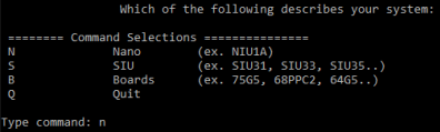
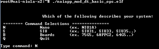
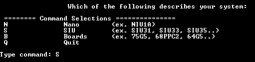
Every NAI sample application asks the same three questions on launch:
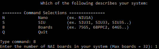
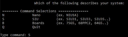
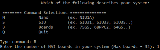
What kind of system do you have? Type N for a Nano (NIU), S for an SIU, or B for a board.
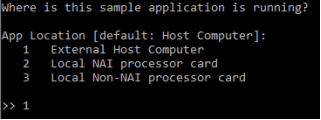
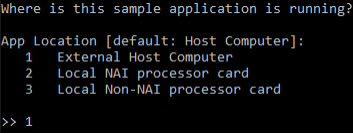
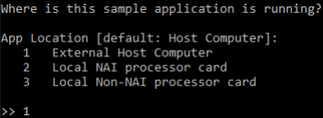
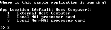
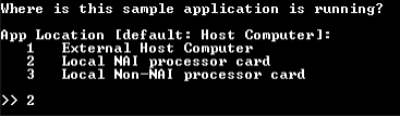
Where is the application running? Type 1 for an external host computer, 2 for the local NAI processor card, or 3 for a non-NAI processor card on the same board.
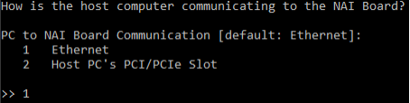
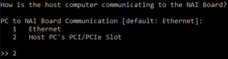
How does the application reach the modules? For external-host setups, choose ethernet or the host’s PCI/PCIe slot. For onboard setups, no further transport is needed — modules are reached over the local hardware.
Your answers fall into one of four scenarios. Pick the scenario that matches your setup and follow the section below.
SIU3x chassis with master cards (e.g., 75G5, 79G5, 68PPC2, 64G5 in legacy chassis; current ARM/Intel masters in newer chassis)
A. External host, ethernet
Your application runs on a host PC and talks to NAI hardware over a network. The NAI Ethernet Listener runs on the target and accepts the connection from your host, then relays commands to the modules. See tools-at-a-glance for the listener’s role and Ethernet How-to FAQ for the default ports.
Single unit (Nano or single NAI board)
flowchart LR
    PC([Host PC<br/>application]) -- Ethernet --> LS[NAI Ethernet Listener]
    subgraph Target [NAI unit]
        LS --> Mods[Local modules]
    end
Reference systems: NIU1A, NIU2A, NIU3A (Nano); any single NAI SBC reachable over ethernet (e.g., 64ARM1, 68ARM2, 68INT6, 75G5).
Walkthrough — Nano (NIU)
Launch the sample app on the host PC, then:
Type N to select Nano.
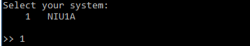
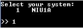
Enter the number that matches your specific Nano.
Select location = 1 (External Host Computer). Hit enter to accept the default.
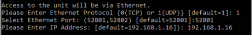
Enter the ethernet port type, port number, and IP address for the Nano. Hit enter at each prompt to accept the default.
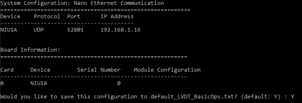
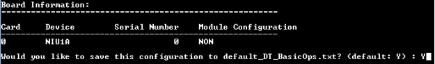
Once connected, the application prints info about the card and modules and offers to save the configuration so you can skip these prompts next time.
Walkthrough — single NAI board
Launch the sample app on the host PC, then:
Type B to select boards, then enter the number of boards in your setup.
Select location = 1 (External Host Computer).
Select communication = 1 (Ethernet).
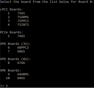
Pick the board type.
Enter the ethernet port type, port number, and IP for the board.
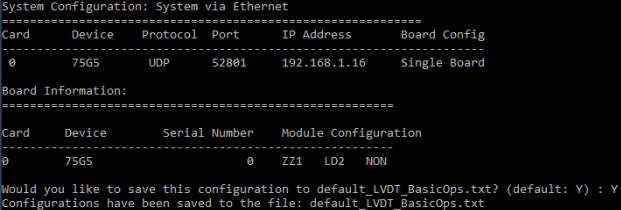
Once connected, the application prints info about the card and offers to save the configuration.
SIU master + backplane slaves
flowchart LR
    PC([Host PC<br/>application]) -- Ethernet --> LS
    subgraph SIU [SIU chassis]
        subgraph Master [Master SBC]
            LS[NAI Ethernet Listener]
        end
        LS -- Backplane bus --> Slave[Slave card<br/>+ modules]
    end
For an SIU, the NAI Ethernet Listener runs on the SIU’s master SBC. Your host PC connects to the master over ethernet, and the master uses the chassis backplane (cPCI, VME, or PCIe depending on the SIU model) to reach modules on slave cards.
Reference systems: SIU31, SIU33, SIU34, SIU35, SIU36, SIU36S — anything in the SIU3x family. Master cards inside the chassis (e.g., 75G5, 79G5, 68PPC2, 64G5 in legacy chassis; current ARM/Intel masters in newer chassis) host the listener.
Walkthrough — SIU master via ethernet
Launch the sample app on the host PC, then:
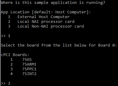
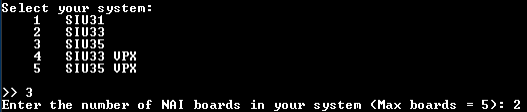
Type S to select SIU.
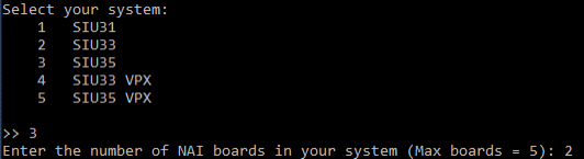
Pick the specific SIU model and enter the number of boards in your chassis.
Select location = 1 (External Host Computer), then choose the master board you’ll be communicating with.
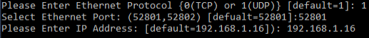
Enter the ethernet port type, port number, and IP address for the master.
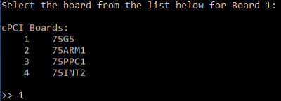
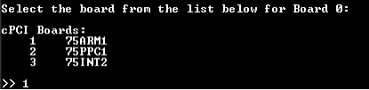
Pick each card on the bus that you want to address. Repeat for the number of cards in the chassis.
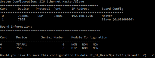
Once the master is connected, it enumerates the cards on the bus and offers to save the configuration.
B. External host, direct bus (PCIe / cPCI / VME)
flowchart LR
    PC([Host PC<br/>application]) -- PCIe / cPCI / VME bus --> Board[NAI board<br/>in host backplane]
    Board --> Mods[Modules]
Your application runs on a host PC, and the NAI board is plugged directly into the host’s backplane (PCIe slot, cPCI chassis, or VME chassis). There’s no ethernet listener in this flow — the host enumerates the board over the bus and the SSK driver speaks to it directly.
Select communication = 2 (the host PC’s PCI/PCIe slot).
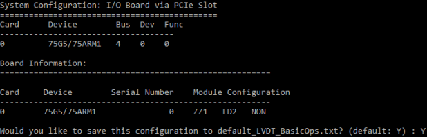
The card is enumerated automatically. Save the configuration so you can skip these prompts next time.
C. Onboard, single SBC
flowchart LR
    subgraph Unit [NAI unit]
        App([Application<br/>running onboard]) --> Mods[Local modules]
    end
Your application runs on the NAI hardware’s own processor — a Nano (NIU) or a single NAI SBC running an onboard OS. There is no network or bus traversal in this flow: the application is on the same processor as the modules, so the menu just needs to know it’s running locally.
On the Nano’s terminal, mark the binary executable:
chmod a+x NAME_OF_APPLICATION.elf
Launch the sample app, then type N to select Nano.
Enter the number that matches your specific Nano.
Select location = 2 (Local NAI processor card) to indicate the application is running on the Nano itself.
The application prints board info and offers to save the configuration. No further connection prompts appear since modules are reached locally.
Walkthrough — onboard a single NAI SBC
The flow is the same as the Nano case but the system answer differs. On the board’s terminal, mark the binary executable:
chmod a+x NAME_OF_APPLICATION.elf
Launch the sample app, then:
At the system prompt, type B for board and enter 1 for the number of boards.
At the location prompt, select 2 (Local NAI processor card).
The application prints board info and offers to save the configuration. No transport prompts appear — modules are accessed locally.
D. Onboard master, backplane slaves
flowchart LR
    subgraph SIU [SIU chassis]
        subgraph Master [Master SBC]
            App([Application<br/>running on master])
        end
        App -- Backplane bus --> Slave[Slave card<br/>+ modules]
    end
Your application runs on an SIU’s master SBC and reaches modules on slave cards over the backplane (cPCI, VME, or PCIe depending on the chassis). No external host and no ethernet listener — the master communicates with slaves directly over the bus.
Reference systems: SIU3x chassis with the application installed on the master SBC (legacy masters: 75G5, 79G5, 68PPC2, 64G5; current ARM/Intel masters in newer chassis).
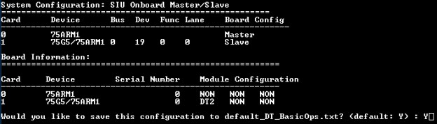
Walkthrough — onboard the SIU master
On the master’s terminal, mark the binary executable:
chmod a+x NAME_OF_APPLICATION.elf
Launch the sample app, then type S to select SIU.
Pick the specific SIU model and enter the number of boards in your chassis.
Select location = 2 (master card) to indicate the application is running on the master itself.
Pick the master card type.
Once the master is opened, it enumerates the slaves on the bus and offers to save the configuration.
Where to go next
ESP2 Quick Start — Code-free testing of modules via NAI’s host-side GUI. Useful for confirming hardware is working before running your own applications.