
Overview
Other user stories: 68INT6 + EM2 in a VPX dev chassis (onboard Ubuntu, backplane PCIe).
Purpose: NAI’s documentation has everything you need to bring up an application, but it’s spread across many guides and the right reading order isn’t obvious. This document stitches those guides into a single, ordered path — from first software exploration to a running application on hardware — using one concrete example so you can see exactly which document to open at each step.
You have a 68ARM2 board with an AD (analog-to-digital) module, and you want to go from a blank slate to a running application — one that hard-codes its menu, sets an AD channel’s range and polarity, reads the channel’s analog value, and prints the reading to the console.
The instructions for each step already exist across NAI’s documentation. What’s easy to miss is the order — which document owns which step, and how you know each step actually worked before you move to the next. This page is that map: it walks the whole journey in sequence, shows you what a successful result looks like at each stage, and links to the document that carries the full procedure. Think of it as the guide that keeps you oriented while the linked docs do the detailed teaching.
This roadmap follows one specific, internally consistent path:
68ARM2 (Zynq) → PetaLinux 2018.2 → PetaLinux Library Software Support Kit (SSK 2.x) → build in Xilinx SDK 2018.2 → transfer with WinSCP → run from a TeraTerm console.
If your board ships a different PetaLinux version, your SSK generation and IDE change with it — see Choosing the Right SSK and Connecting to Boards for the other paths. Otherwise, the page assumes nothing: at every stage it shows the concrete sign that things are working, so even if you’ve never touched an embedded board before, you can always tell whether you’re on track before moving on.
The journey at a glance
The Tool column names everything you’ll need to have installed; each stage links to the document that owns the detail. The stages themselves are written out below the table.
| # | Stage | Tool | Where the details live |
|---|---|---|---|
| 1 | Explore in software | ESP 2.0 | Embedded Soft Panel 2 Quick Start |
| 2 | Pick your SSK package | — | Choosing the Right SSK |
| 3 | Set up the dev environment | Xilinx SDK 2018.2 | ARM Linux Quick-Start Guide |
| 4 | Connect to the board | TeraTerm + WinSCP | Connecting to Boards |
| 5 | Explore modules and read the hardware docs | ESP 2.0 | AD Module Guide, 68ARM2 Manual, AD4 Manual |
| 6 | Build the sample project | Xilinx SDK 2018.2 | ARM Linux Quick-Start Guide |
| 7 | Write your AD application | Xilinx SDK 2018.2 | AD BasicOps |
| 8 | Deploy and run | WinSCP + TeraTerm | Running Applications from the Target |
1. Explore in software first (ESP 2.0)
Before you order hardware, install a toolchain, or write a line of code, you can already see what an AD module does — and ESP is how. The Embedded Soft Panel 2 is a GUI that connects to a board and lets you read and write registers, configure channels, and operate modules without writing anything. Its best feature for a newcomer is that it runs against demo sessions, so you can explore an AD module with no physical board in front of you and nothing to break.
Download ESP from the Downloads page (it’s a separate download from the SSK) and launch it. You’ll open on a Home Menu; choose New Configuration (Simple) and a tab titled “Simple Configuration Menu” appears. From there you pick the number of boards, then the board type (shown at the top as “Board: #”), then how you’re connecting. In a demo session you can do all of this with no hardware attached — the module’s channels appearing on screen is your sign it’s working.
Once an AD module is open, set a channel’s range and watch its measured value update. Then open the API Logger: every action you just took in the GUI is written out as the underlying API call in a .txt log. This is the quietly valuable part — the configuration you clicked through is now shown to you as code, the same code you’ll recognize when you reach AD BasicOps in Step 7. The full walkthrough, with a screenshot of each screen, is in the Embedded Soft Panel 2 Quick Start Guide.
You’re on track when: ESP is open, you’ve reached an AD module through a demo or live session, changed a channel’s range and seen its value respond, and spotted your actions recorded in the API Logger. The module’s channels, ranges, and readings are now concrete rather than abstract.
2. Pick your SSK package
ESP showed you the module; now you need the software kit that lets your own program talk to it. NAI ships the Software Support Kit (SSK) in two generations — 1.x and 2.x — each with several OS-specific packages, so “download the SSK” is really a short decision. The good news is you don’t have to reason it out alone: Choosing the Right SSK has an interactive picker that asks three or four questions — what board, what OS, where your application runs — and names the exact package plus its download link.
For this journey the answer is fixed, and it’s worth seeing why so the result looks right rather than mysterious: a 68ARM2 is a Zynq-based single-board computer running PetaLinux 2018.2, and that combination resolves to the PetaLinux Library Software Support Kit (SSK 2.x). When the picker (or the quick-reference table further down that page) lands you on a package with that exact name, you’ve chosen correctly. PetaLinux itself is bundled inside the download, so there’s nothing separate to fetch.
Download it from the Downloads page, then open the NAI SSK 2.x Package Guide and skim the folder layout before you dig in. Recognizing the top-level folders now — the libraries, the board-support package, the sample source, the headers — means that when a later step says “the AD sample lives in the app-source folder,” you’ll know exactly where to look. That recognition is the sign you’re oriented inside the package, not lost in it.
You’re on track when: you’ve downloaded a package named PetaLinux Library Software Support Kit (SSK 2.x), unpacked it, and can point to its main folders after a look through the Package Guide.
3. Set up the development environment
You have the SSK; now you need the tools that turn its source into something the board can run. For a PetaLinux 2018.2 target that’s Xilinx SDK 2018.2 — the IDE and cross-compiler that build an ARM .elf on your Windows PC. The version tracks the PetaLinux version from Step 2 (a 2018.2 board uses SDK 2018.2; a 2023.2 board would use Vitis Classic 2023.2 — the same tool, later renamed), so matching them is the thing to get right here.
The ARM Linux Quick-Start Guide (PetaLinux 2018) walks the install and toolchain setup end to end, including getting Xilinx SDK itself; the Software Development Guide 2.X covers the same setup from the SSK side if you prefer. Work through it, then import the SSK projects into your workspace. The confirmation that it worked is immediate and visual: your workspace fills with the NAI projects — you’ll see entries such as nai_libs-naibrd, nai_libs-naiether, naiapp_common, and nai_bsp-naibsp — and they import with no red error markers beside them.
(If your application will instead run on a Windows host and reach the board over ethernet, that’s a different route — the Windows CMake Quick-Start Guide — but this roadmap follows the onboard cross-compile flow.)
You’re on track when: Xilinx SDK 2018.2 is installed and the NAI SSK projects appear in your workspace and import cleanly. The environment can now compile for the 68ARM2.
4. Connect to the board (TeraTerm and WinSCP)
With the SSK building on your dev PC, the next job is to make the board reachable — everything from here on happens over two channels you set up now: a serial console for typing commands and reading output, and a file-transfer link for moving the executable across. If you’ve never brought up an embedded board before, the good news is that this stage gives you constant feedback: at nearly every step the board tells you whether you’re on track. Here’s what “on track” looks like at each one.
Cable up. Connect power, an ethernet cable to your host network, and a serial cable. One thing that surprises first-timers: on most NAI ARM boards the serial console and primary ethernet both come out of the front HDMI connector, through a small NAI adapter that splits it into a DB-9 serial port and an RJ-45 jack. So if you were looking for two separate ports and found one HDMI socket, that’s expected — the adapter is where your serial and ethernet cables actually plug in. Connecting to Boards shows the connector and adapter and gives the exact pinouts.
Open the serial console in TeraTerm with NAI’s standard settings — 115200 baud, 8 data bits, no parity, 1 stop bit, no flow control — then apply power to the board. You’re watching for one thing: text scrolling down the terminal within a few seconds. That’s PetaLinux booting, and seeing it means your serial link is correct. When boot finishes you’ll reach a login prompt; log in with user root, password root, and you’ll land on a prompt like this:
root@68arm2-bsp:~#
If you see that prompt, you have a working console into the board. (A blank screen or scrambled characters just means the baud rate or COM port doesn’t match the settings above — the board is fine; re-check and reconnect.)
Confirm the board’s IP. NAI ARM boards store their network settings in motherboard EEPROM, and the on-board naiMBEEPROMUtil reads them from that console. Run:
root@68arm2-bsp:~# naiMBEEPROMUtil formatteddisplay
and look for the board’s own address in the output:
0038:  Eth-A IPv4Address     :192.168.1.16:
003c:  Eth-A IPv4SubnetMask  :255.255.255.0:
0040:  Eth-A IPv4Gateway     :192.168.1.1:
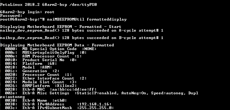 That is the board telling you its IP. If it’s on the same subnet as your PC, you’re set; if not, set it with
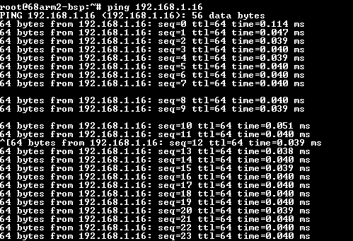
 naiMBEEPROMUtil set EthA_IPv4Address <ip> and reboot (change only the IP, subnet, and gateway fields). Now prove the connection end to end — from your PC’s own command prompt:
> ping 192.168.1.16
Replies coming back is the confirmation that your PC and the board can actually talk to each other. That reachability is the thing every later step depends on.
Set up WinSCP now, while the board’s IP is already in front of you — the transfer itself waits until Step 8, but connecting the tool now means Step 8 is just a drag-and-drop. Create an SFTP session to the same IP (e.g. 192.168.1.16), port 22, username root, password root. When it connects, you’ll see a two-pane window — your PC’s files on the left, the board’s filesystem on the right. That two-pane view appearing is your confirmation that WinSCP is talking to the board; you don’t move anything yet.
You’re on track when: boot text scrolled past in TeraTerm, you reached the root@68arm2-bsp:~# prompt, naiMBEEPROMUtil formatteddisplay showed the board’s IP, ping got replies, and WinSCP shows the board’s files in its right pane. Every one of those is the board or your PC confirming a live link — together they mean the hardware is ready for the rest of the journey.
5. Explore modules and read the hardware docs
With the environment ready, take a short detour back to the hardware, because the code you write next has to match the exact AD part in your board. Between ESP and the manuals you can nail down what you have. In ESP, look at the modules the board reports — your AD module will be listed among them — and note which one it is.
Then confirm the details in the documentation. The AD Module Guide opens with an at-a-glance table of the whole family, so you can see where your part sits: an AD4, for example, is a 16-channel, 16-bit module with multiplexed SAR sampling and a ±10 V range (switchable to ±25 mA current), while an AD1 trades channel count for 24-bit sigma-delta resolution, and an AD3 reads a ±25 mA current loop only. Once you know your member, the AD4 Manual gives its channels, input ranges, and filter and status behavior, and the 68ARM2 Manual covers the board it plugs into and how the module is addressed. Reading a manual section with that same module open in ESP — change a setting, watch the effect — is the fastest way to make it real.
Because an AD channel is a differential analog input — effectively a precise voltmeter wired across your signal — it helps to see the connection in the flesh. On a 44-pin I/O breakout, an AD4’s Channel 1 lands on pin 2 (IN_CH01+) for the high side and pin 24 (IN_CH01-) for the return, so the two wires below go there. Pin numbers come from the 44-Pin I/O column of Appendix C, Pin-Out Details in the AD4 Manual — a different connector or module slot uses different pins, and the 68ARM2 Manual shows which connector your board breaks out.
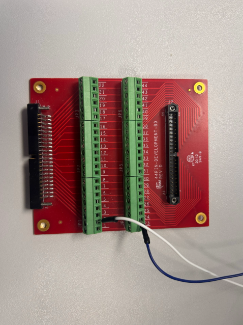
You’re on track when: you can name your exact AD part, state its channel count and input range, and know how it’s addressed on the 68ARM2 — the facts your application will encode.
6. Build the sample project in Xilinx SDK
Before writing anything of your own, build one of NAI’s provided sample projects from start to finish. For a newcomer this is the most reassuring step in the whole journey: a clean build of code you know is good proves your SDK, toolchain, SSK, and board settings all line up — so if your own build later throws an error, you can trust the problem is your change, not the setup.
Follow Importing and Building Sample Applications in the ARM Linux Quick-Start Guide. The one choice to make deliberately is the build configuration, which comes in Zynq and UltraScale forms — for a 68ARM2 you pick Zynq, and you’ll name the configuration something like Debug-Zynq-68ARM2. (UltraScale is for parts like the 64ARM1 and NIU3A, so if you see “UltraScale” in a dialog, that’s simply the other branch, not your board.) Kick off the build and watch the Console tab: compile progress scrolls by, and when it finishes a Debug-Zynq-68ARM2 folder appears with the build output inside. That folder, plus a Console with no errors, is your confirmation.
You’re on track when: a provided sample builds cleanly for the Zynq / 68ARM2 configuration and its output binary sits in the Debug-Zynq-68ARM2 folder. Your whole toolchain is now proven.
7. Write your AD application
Now build the thing you set out to make — an app that hard-codes its menu, sets an AD channel’s range and polarity, reads the channel’s analog value, and prints the reading to the console. Don’t start from an empty project. Copy AD BasicOps, the AD sample from the last step, and work subtractively: it already opens the board, finds the modules, and configures AD channels, so you keep the parts you need and delete the rest. Starting from working code means you always have something that builds to fall back on.
Read AD BasicOps first — it walks the code section by section, and it’s your reference for the two pieces at the heart of your app: setting a channel’s range and polarity, and reading its converted value. Use the NAI SSK 2.x Package Guide to find where the sample’s source lives so you know which files you’re editing. AD BasicOps is written in the current 2.x style, so treat it as your model whenever another example looks different — following one consistent pattern is what keeps a first project from getting tangled.
For the hard-coded board menu, the Board Access sample and the examples in Connecting to Boards show how to open a handle and identify the board. One concrete detail that saves real time: to hard-code the board’s name you use the built-in constant NAI_DEV_NAME_68ARM2 rather than typing the string “68ARM2” yourself — when you spot that constant in the code, you’ve found the right hook.
Because “writing code” doesn’t produce a screen you can match against a picture, your confirmation here is the same one from Step 6: the project builds cleanly to an .elf. If it still compiles after your edits, your trimmed-down app is structurally sound.
You’re on track when: your application compiles to an .elf for the 68ARM2, and you can point to the line where the channel’s range and polarity are set and the line where its value is read.
8. Deploy and run on the target
This is the payoff, and it’s quick because Step 4 already did the setup. Your .elf is on the PC; you need it on the board, made executable, and launched from the console.
Open the WinSCP session you configured in Step 4 (SFTP to 192.168.1.16, root / root). You’ll see the two-pane window again — your PC on the left, the board on the right. Drag your .elf from the left pane into the board’s /home/root/ directory on the right; for a sample-sized app it copies in a second or two, and it appearing in the right pane is your confirmation it’s on the board. (If the panes don’t show, the session just needs reconnecting — the transfer only works while WinSCP is connected over SFTP.)
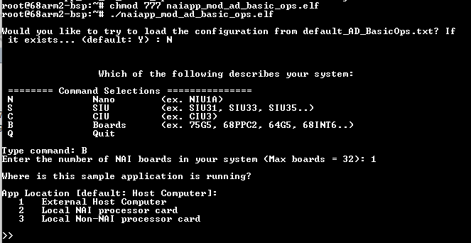
Now switch to your TeraTerm console. Navigate to where you dropped the file, make it runnable, and launch it:
root@68arm2-bsp:~# chmod 777 your_app.elf
root@68arm2-bsp:~# ./your_app.elf
NAI sample-derived apps open with a short configuration menu asking what kind of system you have, where the app is running, and how it reaches the modules. For an app running on the 68ARM2 you’ll answer that it’s a board, running on the local NAI processor — Running Applications from the Target explains each prompt and the right answers. Answer them, and your own hard-coded menu takes over.
You’re on track — and done — when: the app runs, your hard-coded menu appears, the board connection is confirmed, and reading the AD channel prints its measured value to the console. That printed reading is the whole journey paying off: your code, on your board, measuring a real signal.
Related
- Embedded Soft Panel 2 Quick Start — code-free exploration (Step 1)
- Choosing the Right SSK — package selection (Step 2)
- ARM Linux Quick-Start Guide (PetaLinux 2018) — environment + build (Steps 3, 6)
- Connecting to Boards — cabling, IP, TeraTerm, WinSCP transfer (Steps 4, 8)
- Software Development Guide 2.X — using the SSK
- AD Module Guide · 68ARM2 Manual · AD4 Manual — hardware reference (Step 5)
- AD BasicOps · Board Access — code scaffolds (Step 7)
- Running Applications from the Target — launching on the board (Step 8)
- User Story: 68INT6 + EM2 in a VPX Dev Chassis — the same journey on an Intel SBC in a multi-board chassis