Overview
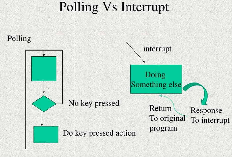
An interrupt is a signal that tells the processor to pause what it’s doing and run a specific piece of code in response to a hardware event. Interrupts are an alternative to polling — instead of your application asking “has anything happened yet?” over and over in a loop, the hardware reaches up and tells your code when something does. Your application stays responsive, and the CPU doesn’t waste cycles checking on quiet hardware.
This guide walks through how interrupts work on NAI hardware, the naibrd_* calls you use to enable and route them, and how the same interrupt setup looks across the four ways an NAI application can be configured (running on a host PC over ethernet, on a host PC over a direct bus, on the NAI processor itself, or on an SIU master). The SSK 1.x and SSK 2.x APIs are shown side-by-side wherever they differ.
Use cases
Interrupts handle events that need attention right away — sensor readings, timer ticks, the end of a serial transmission, fault conditions.
- Defense: Real-time radar returns, weapons-bus traffic, fault detection on flight-critical subsystems.
- Commercial: End-of-message handling, button presses, and other UI events that need low-latency response.
- Industrial: Overvoltage and overcurrent detection, equipment fault alerts, condition monitoring.
Features at a glance
- Edge and level triggers on every interrupt source — pick the one that matches how the event behaves.
- 32-bit vector numbers that uniquely identify which source fired, so a single handler can serve many events.
- Interrupt steering that routes each signal to wherever your application is running — PCIe, VME, ethernet, or the NAI processor onboard.
- Multiple ISRs — give each source its own handler if you want, dispatched by the steering hardware.
- Low-latency delivery — typically under 5 ms end-to-end on an NAI ARM platform.
Theory of Operation
When an interrupt fires, the processor pauses whatever it was doing, saves its state, and jumps to a function you’ve registered called the Interrupt Service Routine (ISR). Once the ISR finishes, the processor picks up where it left off. The hardware’s job is to notify; the ISR’s job is to handle.
Level vs edge triggers
NAI modules let you choose how an interrupt source behaves — per source, not per module:
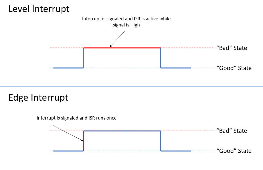
- Level-triggered — the interrupt stays asserted as long as the underlying condition is true. The processor keeps re-entering the ISR until your code clears the condition at the source. Use level for “this state is wrong and will stay wrong until something fixes it” — overcurrent, fault flags, stuck signals.
- Edge-triggered — the interrupt fires once on a specific signal transition (rising or falling edge), then assumes the system is back to normal. Use edge for discrete moments — a byte arriving, a measurement completing, a threshold getting crossed.
Vector numbering
Every interrupt source on an NAI board has a vector number — a 32-bit value that uniquely identifies which event fired. When the source fires, the same vector value is passed as the argument to your ISR, so one handler can recognize and dispatch on many different sources.
The vector value itself is yours to assign. There’s no fixed format; you pick a scheme that lets your ISR decode which (card, module, channel, event) triggered. A common pattern is to pack those fields into the 32 bits:
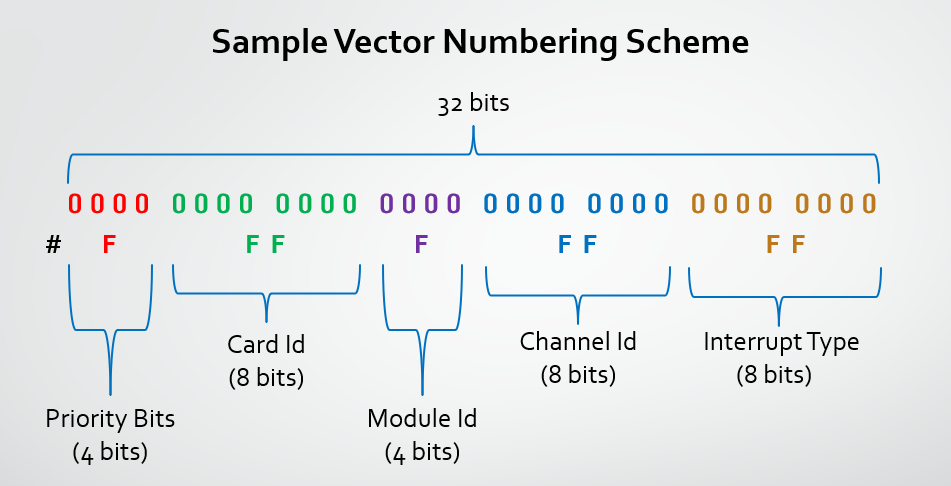
- Priority — relative urgency, if your application uses it
- Card ID — which card on the bus
- Module ID — which slot on the card
- Channel ID — which channel on the module
- Interrupt Type — what kind of event (TxComplete, RxReady, BIT fault, etc.)
- Extra Information — free-form, sometimes used for sub-event detail
You write the vector you want into the module’s interrupt-vector register up front, and it gets handed back to your ISR every time the source fires.
Steering and multiple ISRs
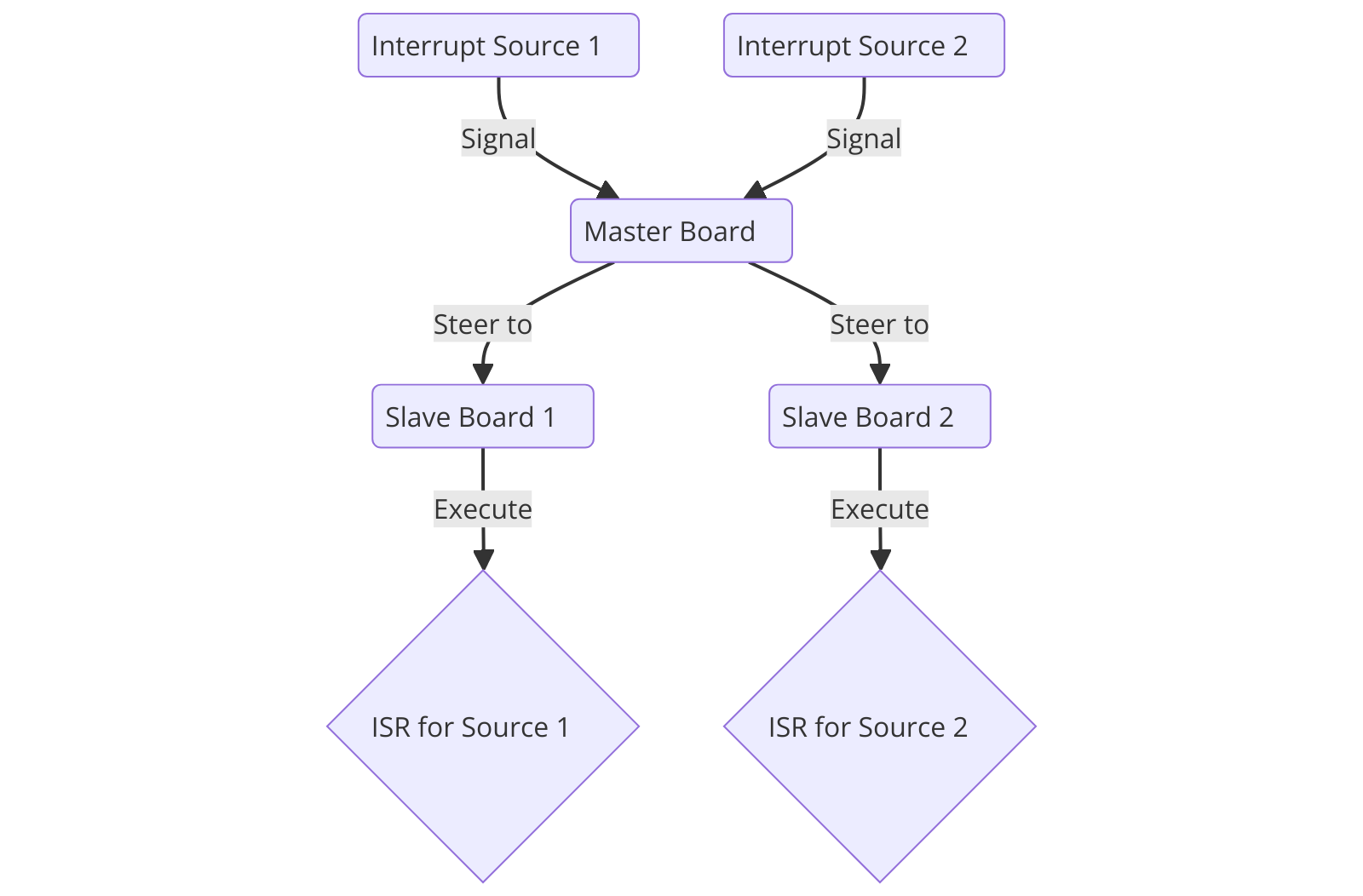
Interrupt steering is the setting that controls where an asserted interrupt actually goes — to a PCI/VME host, out over ethernet to a remote host (as an IDR — see below), or to the NAI processor on the board. You set the steering per module, and it has to match where your application is running for the interrupt to reach your code.
If you want different events to run different handler functions, you can register multiple ISRs and let the steering hardware route each one to its handler — the Multiple ISR pattern.
Latency
An interrupt passes through a few layers before your ISR runs:
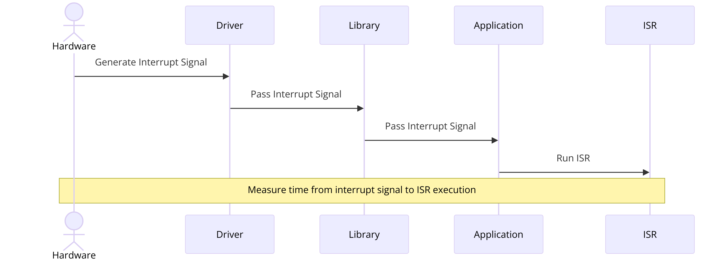
- The hardware generates the interrupt signal.
- The driver layer receives the signal from the bus, network, or onboard controller.
- The SSK library layer dispatches it to the handler you registered.
- Your application’s ISR runs.
To measure end-to-end latency on your own system: have the ISR capture a timestamp on entry, log a timestamp at the moment you trigger the event, and subtract. A typical NAI ARM platform measures around 4.7 ms, which is fast enough for most real-time applications.
How NAI delivers interrupts
How an interrupt physically reaches your code depends on where your application is running. The four cases match the four configurations covered in Running Applications from the Target:
| Application location | How interrupts get to your code | Key API |
|---|---|---|
| External host PC, ethernet to the board | Ethernet IDR (Interrupt-Driven Response). When an interrupt source on the board fires, the board sends a UDP or TCP packet containing the vector to a port your host is listening on. | naibrd_Ether_SetIDRConfig + EnableIDR (see Ethernet IDR alternative) |
| External host PC, direct PCIe / cPCI / VME bus | OS-level bus interrupt. The board asserts an interrupt on the host bus, the host OS routes it to the SSK driver, and the SSK calls your ISR. | naibrd_ConnectISR (2.x) / naibrd_InstallISR (1.x) |
| NAI processor (application running onboard) | Onboard ISR. Same Connect/Install pattern as the bus case, but the interrupt routes through the NAI processor’s local interrupt controller rather than crossing a host bus. | naibrd_ConnectISR (2.x) / naibrd_InstallISR (1.x) |
| NAI master SBC with backplane slaves | Steered onboard ISR. Interrupts from slave cards are routed via steering to the master, where one ISR catches them all and uses the vector to figure out which slave fired. | Per-module steering call + naibrd_ConnectISR / naibrd_InstallISR |
Polling is always an option — your code reads status registers in a loop instead of registering an ISR. It’s simpler and avoids dispatching overhead, but you’ll miss events that fire faster than your loop, and you can’t do other work while polling. Interrupts win when timing matters or when the CPU has other things to do.
Note
Some operating system targets need a bit of additional setup before interrupts will actually be delivered to your application. On the Kismet Deos SSK, for example, the project’s process-developer XML must enable the
naibsp_sys-attach-interruptfeature — the Jupiter Deos SSK’s interrupt samples work as-is, and adding that feature there causes build errors. The module-side setup described in this guide is necessary but not always sufficient. The OS-specific sections of the Software Development Guide cover whatever extra steps your platform needs.
Enabling interrupts on a module
Every NAI module family follows the same four-step pattern to turn an interrupt on:
- Pick the event type you want to be notified about — for a discrete input, that might be “low-to-high transition”; for a serial channel, “receive FIFO not empty.”
- Set a vector — the value the module will hand to your ISR when this event fires.
- Set the trigger — edge or level (covered in Theory of Operation).
- Enable the interrupt on the channel.
Once you’ve done all four, the module starts asserting its interrupt line whenever the event you picked happens, and your ISR catches it. Miss any of the four and nothing happens.
/* SSK 1.x — DT family pattern */
naibrd_DT_SetGroupInterruptVector(cardIndex, module, group, type, vector);
naibrd_DT_SetEdgeLevelInterrupt(cardIndex, module, channel, type, NAI_DT_EDGE_INTERRUPT);
naibrd_DT_SetInterruptEnable(cardIndex, module, channel, type, true);
/* SSK 2.x — DT family pattern */
naibrd_DT_SetChanMappedInterruptVector(cardIndex, module, type, vector);
naibrd_DT_SetChanMappedInterruptTriggerType(cardIndex, module, channel, type, NAIBRD_INT_TRIGGER_TYPE_EDGE);
naibrd_DT_SetChanMappedInterruptEnable(cardIndex, module, channel, type, true);The pattern is the same across module families — swap the module prefix (AD, AR, CAN, DA, DIF, DS, DSW, DT, ENC, RG, RTD, RLY, SER, SD, TTL, etc.) and the names line up. The status type enum (which events the family supports) is per family, so the values change too — what SSK 1.x calls NAI_DT_STATUS_LO_HI_TRANS_LATCHED is NAIBRD_DT_STATUS_LO_HI_TRANS_LATCHED in SSK 2.x, and each event type comes in both a _LATCHED (sticky) and a _REALTIME (live) variant. The Per-module reference below summarizes which families do what, and each module’s manual lists every event type that family supports.
A few specific differences between the versions are worth knowing up front:
- Trigger type. SSK 1.x uses a per-family enum like
nai_dt_interrupt_twith valuesNAI_DT_EDGE_INTERRUPT/NAI_DT_LEVEL_INTERRUPT. SSK 2.x replaces it with one cross-family enum,naibrd_int_trigger_type_t, with valuesNAIBRD_INT_TRIGGER_TYPE_EDGE/_LEVEL. The behavior is the same; only the name and where it’s defined changed. - Vector and steering granularity. In SSK 1.x, vector and steering are set per (module, group, type), where a group is a collection of channels on the module that share vector and steering settings. In SSK 2.x there’s no group at the API level — vector and steering are set per (module, type). Enable and trigger type stay per (channel, type) either way.
- Channel-mapped vs event-mapped (SSK 2.x). Most module families fire interrupts on per-channel events (“channel 3 saw a low-to-high transition”). A few families also fire interrupts on module-level events that aren’t tied to a single channel (“the serial receive FIFO crossed its threshold”). SSK 2.x splits these into two separate call families —
…SetChanMappedInterrupt…for the per-channel kind and…SetEventMappedInterrupt…for the module-level kind. The DT family in the example above only uses channel-mapped; the SER family uses both.
Installing the ISR
Configuring a module gets the interrupt to fire. Installing an ISR is what makes your code actually run when it does.
/* SSK 1.x — ISR signature on Windows / Linux */
typedef void (NAICALLBACK *nai_isr_t)(void* param, uint32_t vector);
/* On VxWorks the signature is single-arg: void (*nai_isr_t)(uint32_t vector) */

void my_isr(void* param, uint32_t vector) {
   /* dispatch on vector to handle the right event */
}

nai_status_t naibrd_InstallISR(int32_t cardIndex, naibrd_irq_id_t irq_id,
                                nai_isr_t isr, void* param);
nai_status_t naibrd_UninstallISR(int32_t cardIndex);

/* Pick the irq_id that matches your steering destination:
 *   NAIBRD_IRQ_ID_ON_BOARD_0   — onboard ARM custom application
 *   NAIBRD_IRQ_ID_ON_BOARD_1   — NAI Ethernet Listener application
 *   NAIBRD_IRQ_ID_VME_LEVEL_1..7 — VME bus, matching the configured level
 *   NAIBRD_IRQ_ID_DONT_CARE    — PCIe / cPCI / anything else where no
 *                                 hardware-IRQ identifier is needed
 */
/* SSK 2.x — single-arg ISR signature on every platform */
typedef void (NAICALLBACK *nai_isr_t)(uint32_t vector);
void my_isr(uint32_t vector) {
/* dispatch on vector to handle the right event */
}
nai_status_t naibrd_ConnectISR(int32_t cardIndex, nai_isr_t isr);
nai_status_t naibrd_DisconnectISR(int32_t cardIndex);Your handler gets the 32-bit vector that the firing source wrote into its vector register — that’s how you know which event happened. SSK 2.x simplifies the install call in three ways: the per-board IRQ identifier is handled internally (no irq_id argument), the ISR signature is single-arg across every platform, and there’s no longer a void* user-param slot (use a global or static if you need to pass state to the ISR).
Bus-specific setup. When your application runs on an external host, the host’s OS also has to be set up to deliver the bus interrupt:
- PCIe / cPCI:
naibrd_GetPCIInterruptConfig(cardIndex, &statusAddr, &clearAddr, &clearVal)returns the addresses the OS driver needs to acknowledge the interrupt at the bus level. On PetaLinux and other Linux distributions, the NAI driver handles this for you; on Windows the same is handled by the NAI PCI driver installer. - VME:
naibrd_SetVMEInterruptLevel(cardIndex, level)sets the VME priority level (1–7). Your host’s VME controller has to be configured to respond at that level for the interrupt to reach your application.
Ethernet IDR alternative
If your application is on an external host and reaches the board over ethernet, there’s no local bus or onboard processor for an ISR to live on. The board can’t push an interrupt directly into your host’s OS the way a PCIe card would. Instead, you configure the board to send a UDP or TCP packet whenever an interrupt source fires — an Interrupt-Driven Response (IDR) — and your host listens on a port for those packets.
You configure the IDR from your host through the SSK ethernet API:
/* SSK 1.x — configure the board to send an IDR packet when this vector fires */
naibrd_Ether_SetIDRConfig(cardIndex, idrId,
                          protocol,       /* 0 = TCP, 1 = UDP */
                          ipLength,       /* 4 = IPv4, 16 = IPv6 */
                          hostIP,         /* your host's IP */
                          hostPort,       /* port your host is listening on */
                          vector,         /* the same vector you set on the module */
                          commandCount,   /* number of follow-on commands to run on fire */
                          arraySize, commands);
naibrd_Ether_EnableIDR(cardIndex, idrId);
Note
SSK 2.x doesn’t expose a single-call equivalent of
naibrd_Ether_SetIDRConfig. Its ethernet stack splits message construction (thenaiether_*library) from interface management (naiif_ether_*), so configuring an IDR under SSK 2.x means building the IDR-config protocol message yourself with thenaiether_*builders and sending it over the open Ethernet connection. The byte-level message format is the same — see NAI Ethernet Protocol APIs for the build / send / decode pattern and NAI Ethernet Protocol Reference for the on-the-wire layout.
Once the IDR is configured, the module-side setup is the same as any other delivery method — set the event type, the vector, and the trigger, then enable. The one extra step is the steering call: it needs to route the interrupt through the ethernet path rather than to the local bus, so the listener picks it up and sends the IDR packet.
Steering and multiple ISRs
Steering is the setting that picks where an asserted interrupt is delivered. It has to match where your application is running, or the interrupt will end up somewhere your code can’t see it. You set steering per module, on the same granularity as the vector (in SSK 1.x with an extra group argument, as covered in Enabling interrupts on a module).
| Steering destination | SSK 1.x value | SSK 2.x value | What it routes to |
|---|---|---|---|
| Onboard ARM custom app | NAIBRD_INT_STEERING_ON_BOARD_0 (2) | NAIBRD_INT_STEERING_ONBOARD_ARM (2) | The NAI processor’s local interrupt controller — use this when your application runs on the NAI board itself or on an SIU master |
| NAI Ethernet Listener | NAIBRD_INT_STEERING_ON_BOARD_1 (3) | (same value 2 — the listener runs on the onboard ARM) | The on-board listener process, which then sends an ethernet IDR packet to your remote host (see Ethernet IDR alternative) |
| VME bus | NAIBRD_INT_STEERING_VME (1) | NAIBRD_INT_STEERING_VME (1) | The VME backplane — for VME-host applications |
| PCIe bus | NAIBRD_INT_STEERING_PCIE_APP (5) | NAIBRD_INT_STEERING_PCIE (5) | The PCIe backplane — for PCIe-host applications |
| cPCI bus | NAIBRD_INT_STEERING_CPCI_APP (6) | NAIBRD_INT_STEERING_CPCI (6) | The cPCI backplane — for cPCI-host applications |
A common pattern on an SIU master with backplane slaves is to steer every slave-card module’s interrupts to the onboard ARM so the master SBC catches them all with a single ISR. The ISR then reads the vector to figure out which slave card and event fired. That’s the multiple ISR pattern in practice — one registered handler, many sources, dispatched by vector.
The steering call has the same shape as the vector call:
/* SSK 1.x */
naibrd_DT_SetGroupInterruptSteering(cardIndex, module, group, type, steering);
/* SSK 2.x */
naibrd_DT_SetChanMappedInterruptSteering(cardIndex, module, type, steering);Worked end-to-end example
Here’s how the pieces fit together. The code below sets up a low-to-high transition interrupt on channel 3 of a DT module sitting in slot 1, on an NAI ARM board where the application is running onboard.
/* SSK 1.x */
#define CARD_IDX        0
#define MODULE          1     /* DT module in slot 1 */
#define GROUP           0     /* channel group on the module */
#define CHANNEL         3     /* discrete input on channel 3 */
#define MY_VECTOR       0x10030001  /* mod 1, ch 3, low-to-high transition */

static void my_isr(void* param, uint32_t vector) {
   /* dispatch on vector — for this example just flag the event */
   /* keep ISRs short; defer heavy work to your application loop */
   (void)param;
}

int main(void) {
   /* Open the device */
   naibrd_OpenDevice(CARD_IDX, NAIBRD_COMM_ONBOARD, NAI_DEV_NAME_NIU1A);

   /* Configure the interrupt on the module */
   naibrd_DT_SetGroupInterruptVector(CARD_IDX, MODULE, GROUP,
                                     NAI_DT_STATUS_LO_HI_TRANS_LATCHED,
                                     MY_VECTOR);
   naibrd_DT_SetEdgeLevelInterrupt(CARD_IDX, MODULE, CHANNEL,
                                   NAI_DT_STATUS_LO_HI_TRANS_LATCHED,
                                   NAI_DT_EDGE_INTERRUPT);
   naibrd_DT_SetGroupInterruptSteering(CARD_IDX, MODULE, GROUP,
                                       NAI_DT_STATUS_LO_HI_TRANS_LATCHED,
                                       NAIBRD_INT_STEERING_ON_BOARD_0);
   naibrd_DT_SetInterruptEnable(CARD_IDX, MODULE, CHANNEL,
                                NAI_DT_STATUS_LO_HI_TRANS_LATCHED, true);

   /* Install the ISR (irq_id matches the ON_BOARD_0 steering) */
   naibrd_InstallISR(CARD_IDX, NAIBRD_IRQ_ID_ON_BOARD_0, my_isr, NULL);

   /* ... your application runs; my_isr() fires on each LO->HI transition ... */

   /* Tear down */
   naibrd_UninstallISR(CARD_IDX);
   naibrd_DT_SetInterruptEnable(CARD_IDX, MODULE, CHANNEL,
                                NAI_DT_STATUS_LO_HI_TRANS_LATCHED, false);
   naibrd_Close(CARD_IDX);
   return 0;
}
/* SSK 2.x */
#define CARD_IDX 0
#define MODULE 1 /* DT module in slot 1 */
#define CHANNEL 3 /* discrete input on channel 3 */
#define MY_VECTOR 0x10030001 /* mod 1, ch 3, low-to-high transition */
static void my_isr(uint32_t vector) {
/* dispatch on vector — for this example just flag the event */
/* keep ISRs short; defer heavy work to your application loop */
}
int main(void) {
/* Open the device */
naibrd_OpenDevice(CARD_IDX, NAIBRD_COMM_ONBOARD, NAI_DEV_NAME_NIU1A);
/* Configure the interrupt on the module */
naibrd_DT_SetChanMappedInterruptVector(CARD_IDX, MODULE,
NAIBRD_DT_STATUS_LO_HI_TRANS_LATCHED,
MY_VECTOR);
naibrd_DT_SetChanMappedInterruptTriggerType(CARD_IDX, MODULE, CHANNEL,
NAIBRD_DT_STATUS_LO_HI_TRANS_LATCHED,
NAIBRD_INT_TRIGGER_TYPE_EDGE);
naibrd_DT_SetChanMappedInterruptSteering(CARD_IDX, MODULE,
NAIBRD_DT_STATUS_LO_HI_TRANS_LATCHED,
NAIBRD_INT_STEERING_ONBOARD_ARM);
naibrd_DT_SetChanMappedInterruptEnable(CARD_IDX, MODULE, CHANNEL,
NAIBRD_DT_STATUS_LO_HI_TRANS_LATCHED, true);
/* Connect the ISR */
naibrd_ConnectISR(CARD_IDX, my_isr);
/* ... your application runs; my_isr() fires on each LO->HI transition ... */
/* Tear down */
naibrd_DisconnectISR(CARD_IDX);
naibrd_DT_SetChanMappedInterruptEnable(CARD_IDX, MODULE, CHANNEL,
NAIBRD_DT_STATUS_LO_HI_TRANS_LATCHED, false);
naibrd_Close(CARD_IDX);
return 0;
}Both versions follow the same overall flow — open the device, set vector, set trigger, set steering, enable, install the ISR — and then tear everything down at the end. What changes between versions is the shape of the per-module calls (SSK 1.x takes a group for the vector and steering calls and uses a DT-specific edge/level enum; SSK 2.x drops the group and uses one cross-family trigger enum) and the install call itself (covered in Installing the ISR).
Per-module reference
The interrupt API surface is the same across module families — each one exposes the same configure-and-enable pattern shown above. What varies family to family is the set of event types you can enable (each module’s manual lists them in its register-map and status-bits sections) and whether the family supports channel-mapped events, event-mapped events, or both. The sample apps below show the full pattern end-to-end in real code.
| Family | Mapping styles | Sample app (SSK 1.x) | Sample app (SSK 2.x) |
|---|---|---|---|
| AD (analog input) | Chan-mapped, Event-mapped | AD_Interrupt | — |
| AR (ARINC 429/575) | Chan-mapped | AR_Interrupt | ar429_interrupt |
| CAN (CANbus) | Chan-mapped | CAN_Interrupt | — |
| DA (analog output) | Chan-mapped | DA_Interrupt | — |
| DIF (discrete differential) | Chan-mapped | DIF_Interrupts | — |
| DS (synchro/resolver simulator) | Chan-mapped | DSW_Interrupt | — |
| DT (discrete) | Chan-mapped | DT_Interrupt | dt_basic_interrupt |
| FT (MIL-STD-1553/1760) | Module-level (BC/RT) | M1553_BC_Interrupt, M1553_RT_Interrupt | m1553_bc_interrupt_fifo, m1553_rt_interrupt |
| RTD (resistance temperature) | Chan-mapped | RTD_Interrupt | — |
| RLY (relay) | Chan-mapped | RLY_Interrupt | — |
| SER (serial) | Chan-mapped + Event-mapped | SER_EtherInterrupts_Tx, SER_EtherInterrupts_Rx | ser_basic_interrupt |
| TTL (TTL discrete) | Chan-mapped | TTL_Interrupt_Ethernet | ttl_basic_interrupt |
For families where the SSK 2.x sample column is blank, the function-call pattern is the same as the closest family that does have one — most module families share the same …SetChanMappedInterrupt… shape, just with their own status-type enum.
Common pitfalls
- ISR is installed but nothing ever fires. The most common cause: one of the four per-module steps (enable, vector, trigger, steering) didn’t get set. Missing any one is silent — no error, no interrupt. Also check that the steering destination actually matches where your application is running: onboard ARM for onboard apps, PCIe/cPCI/VME for external bus hosts, and the listener for ethernet IDRs.
- Two sources fire the same vector. When that happens, your ISR can’t tell them apart. Encode the (module, channel, event type) triplet into the vector value so every source has a unique one — that’s what the typical vector layout in Vector numbering is for.
- Edge interrupt seems to stop firing. Edge-triggered interrupts fire once on a transition and then wait for the next transition. If the underlying state never goes back to “normal,” there’s nothing for the edge to detect next time. Check that your ISR (or some other code) is clearing the underlying condition on the module so a new edge can happen.
- Level interrupt fires over and over. The opposite problem. A level-triggered interrupt re-asserts the moment your ISR returns if the condition is still true. Clear the condition on the module — usually a status-register acknowledge — inside the ISR before returning.
- Polling and interrupts conflict on the same source. You can use both in the same application, but not on the same source — if a polling loop reads and clears a status register that the ISR was about to handle, the ISR sees nothing when it runs. Pick one mechanism per source.
- Platform-specific setup hasn’t been done. Some operating system targets need extra configuration before interrupts will be delivered to your code. On the Kismet Deos SSK in particular, the project’s process-developer XML must enable the
naibsp_sys-attach-interruptfeature (the Jupiter Deos SSK’s interrupt samples work as-is — adding it there causes build errors). If the module side is set up correctly and the ISR still isn’t getting called, check the OS-specific sections of the Software Development Guide (or the 1.x version) for what your platform needs. - There’s a separate enable somewhere else. Some module families have a per-channel status-enable bit that gates whether status events fire interrupts at all. If everything on this guide is set and you’re still seeing nothing, check the module manual’s status-register chapter for that family.
- External host isn’t catching ethernet IDRs. Confirm that the NAI Ethernet Listener is actually running on the board, and that the IDR is configured with your host’s correct IP and port. Ethernet How-to FAQ covers the listener and its default ports.
Related Resources
- Connecting to Boards — power, network, terminal, and file transfer to your board (the prerequisite for any of the setup in this guide)
- Opening a Software Handle to Your Board — open the
naibrd_*connection your interrupt-configuration calls run against - Running Applications from the Target — load and launch on the board; covers the four application-location scenarios this guide maps interrupt delivery onto
- NAI Ethernet Protocol Overview · APIs · Reference — concepts, SSK calls, and byte-level layout for ethernet IDR setup and other ethernet operations
- ESP2 Quick Start — exercise interrupt-capable modules through the GUI before writing code
- Software Development Guide 2.X · Software Development Guide 1.X — platform-specific build, deploy, and any OS-level interrupt setup
- SSK 1.x Package Guide · SSK 2.x Package Guide — what’s in each SSK
- Module manuals — every module’s manual lists its interrupt event types and channel/event mapping in its register-map and status-bits sections