This guide will explain how to use the NAI Software Support Kit 2.X alongside other tools from NAI to develop your application.
NAI SSK 2.x is intended for use with boards such as: 68G6, 68ARM2, 68ARM4, 68INT6, NIU3A.
If you have not already NAI recommends using the NAI Embedded Soft Panel to kickstart development. Via a GUI it allows users
to quickly configure and operate NAI products. The API Logger tool within the NAI Embedded Soft Panel will allow you to kickstart
writing your program as it will record the API calls made as you use the GUI to configure and operate your hardware.
If you do not yet have your hardware you can still use the NAI Embedded Soft Panel to kickstart your development via the Demo Panel.
If you do not yet know details about your hardware and have already started using the NAI Embedded Soft Panel
you can skip to Starting Development. If you want help
setting up the environment you can simply pick your preferred OS and follow the corresponding instructions before continuing to Starting Development.
The code you write will be fully portable.
To download the NAI Software Support Kit click here.
Environment Setup
These sections will explain how to setup your environment to begin development for your chosen OS.
If you do not know what OS you will use yet simply pick your preferred OS, all written .c files will are fully portable.
Select the All OS installer to begin download, then run the installer. The tool that will be used for development is Xilinx SDK 2018.2, which is included in the Vivado Design Suite installation.
Select the Windows Self Extracting Web Installer to begin download, then run the installer. The tool that will be used for development is Vitis Classic 2023.2, which is included in the Xilinx unified installation.
CMake 3.22.1 or later must be installed to build the Windows SSK. Building CMake for Windows will generate all necessary Visual Studio project files and an nai_ssk.sln file.
Using a command window:
cd into the ssk2/build directory
run the following command to configure all projects:
To generate project files for a different version of Visual Studio, enter a different generator name (e.g. Visual Studio 15 2017). Use cmake —help to explore configuration options.
The nai_ssk.sln file now exists in the build directory of the SSK and can be opened in the Visual Studio version targeted in the prior step.
CMake 3.22.1 or later must be installed to build the Linux SSK. Using any web browser, navigate to https://cmake.org/files/v3.22 and download the “cmake-3.22.1-linux-x86_64.tar.gz” package.
The NAI Software Support Kit currently supports the following versions of VxWorks 7:
SR660
22.09
23.03
23.09
24.03
The SSK is intended for use with the Wind River Workbench development environment. Please contact Wind River with any questions about obtaining a VxWorks license or installing Wind River Workbench.
Please contact DDC-I to obtain a copy of the DDS(DDC-I Developer Suite). Once installed, launch the OpenArbor IDE to start working with the NAI Software Support Kit.
If you have not already NAI recommends using the NAI Embedded Soft Panel to kickstart development. Via a GUI it allows users
to quickly configure and operate NAI products. The API Logger tool within the NAI Embedded Soft Panel will allow you to kickstart
writing your program as it will generate and save the API calls you make via the GUI as you configure and operate your hardware.
Now that your enviroment is set up and your project has been configured according to your hardware you can begin development.
If you do not know yet what hardware you will be using you can begin development now and go through configuration later.
The development process is universal for all configurations.
For development we will be using the NAI Software Support Kit.
NAI recommends that you begin with our selection of sample applications. The full collection can be found here.
First select a sample application from the family that you wish to develop for. For the sake of example we will use the discrete I/O family.
The particular file we are using is DT_BasicOps.c
While the precise functionality is specific to the discrete I/O family, most sample applications use a similar structure.
While reading this section please read along in the source code here at the
same time to best understand how to then develop your own application.
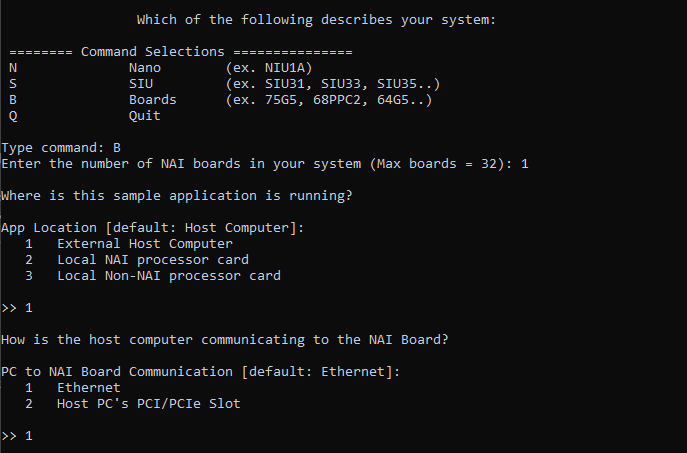
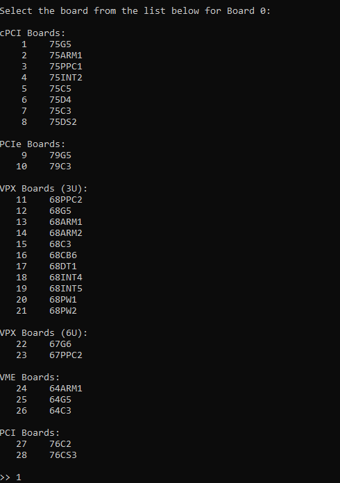
Once you run the sample application you will be presented with a configuration menu. The first question
will ask what your system is.
Nano
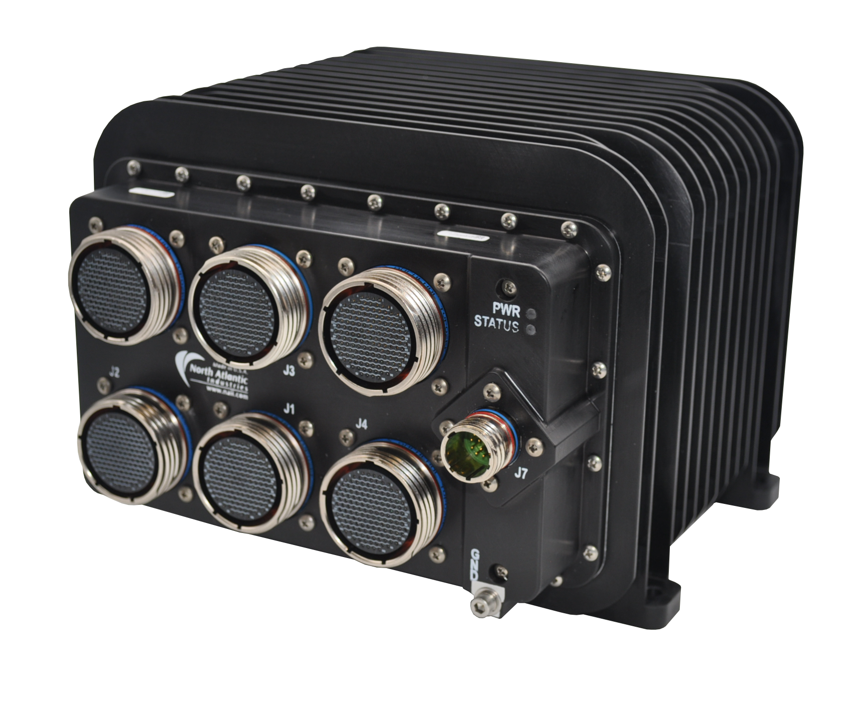
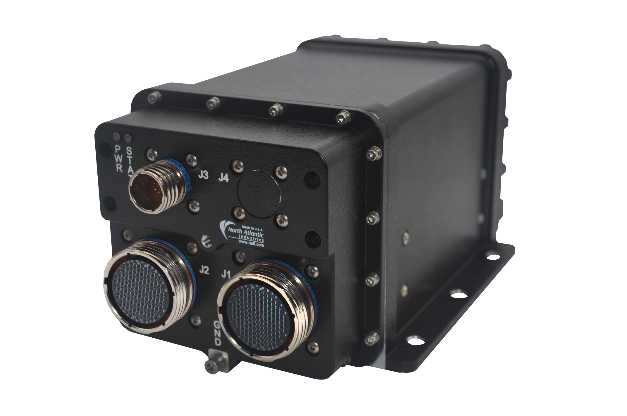
A Nano unit is a small, rugged multifunction I/O system.
SIU
An SIU is a large rugged system containing multiple open backplane boards.
Board
A board is a single board computer.
In this example we are using a board so we input B. We then selected the board we were using, a 75G5.
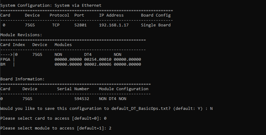
To connect you then must enter what ethernet protocol you are using, your type of ethernet port,
and the IP address of the board.
If all of the above information was correct you will then connect to the board and see
the following configuration menu.
Please then select which module you would like to configure.
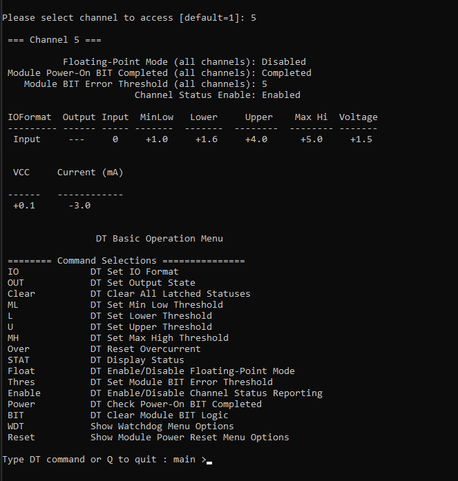
We then selected which channel we would like configure and the following configuration menu opened, containing all of the settings to configure the module’s channel.
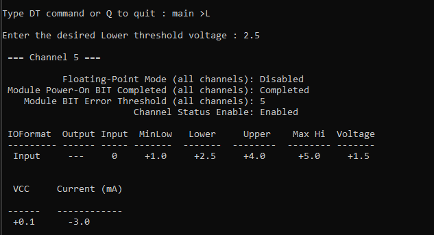
As an example we then selected DT Set Lower Threshold Voltage and made our configuration change.
With this sample application as the basis please refer to other sample applications for more information.
While this sample application was a configuration app there are also specific examples of how to use features of a given module.
For example if you want to implement ethernet IDR
with discrete I/O NAI offers a corresponding sample application.
Once you have completed your application and want to test it it is time to build and export your program.
Connecting to the System
To learn how to get connected via the Software Support Kit please click here.
To set up a remote serial and ethernet connection please follow the following steps.
Remote Connection
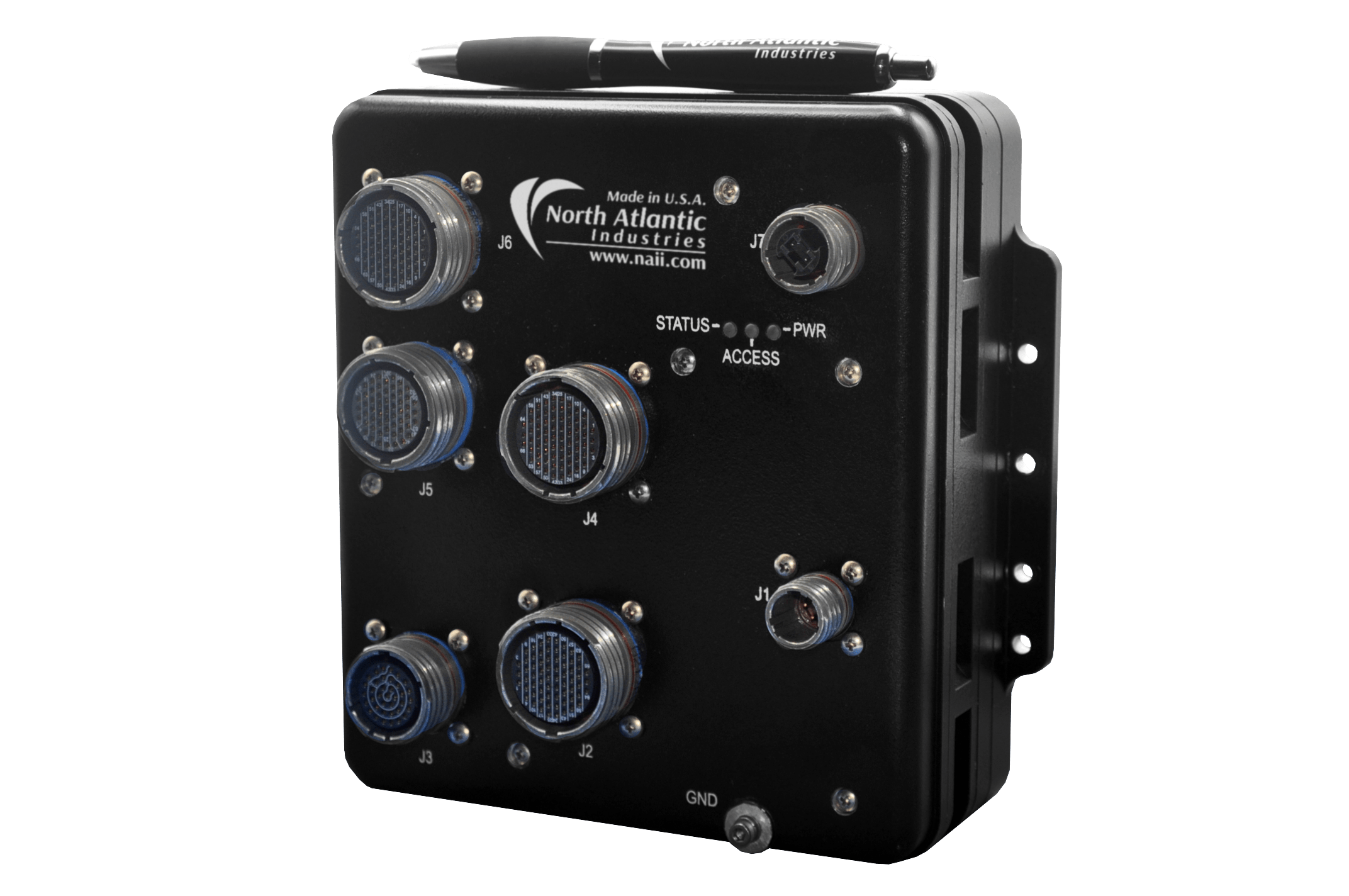
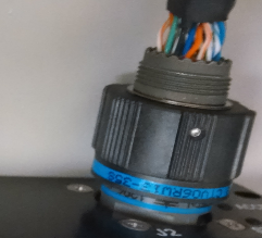
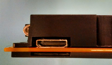
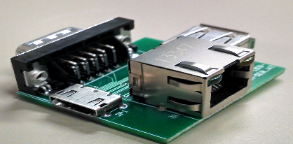
The serial connection and Ethernet port are accessed through the HDMI connector on ARM target boards. For ruggedized ARM enclosures, both ports are routed to a MIL connector. You may need an external adapter board (see below) to convert the HDMI connector to a serial and Ethernet port.
CAUTION
Ensure that target board is powered off, until directed to power it on.
HDMI Connector
MIL Connector
Note
The USB-A connector on the adapter board is not supported by the ARM target board.
Adapter Board
Serial Port
Install minicom through the terminal:
|$ sudo yum install minicom
Check for all available serial ports:
|$ dmesg \| grep tty
Run minicom with the desired serial port.
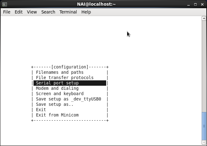
|$ sudo minicom -s /dev/<Serial Port>
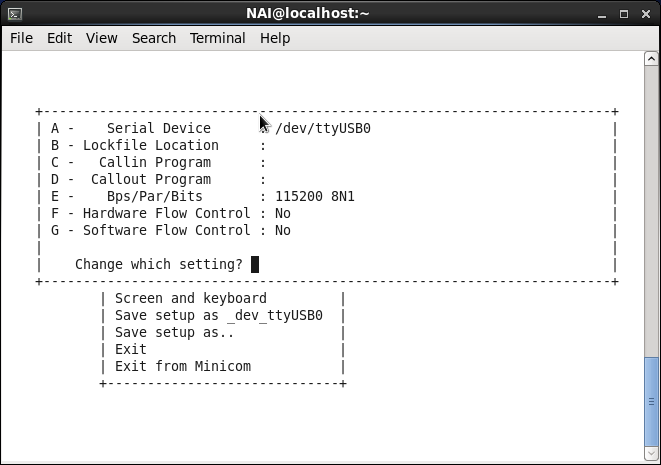
Select ‘Serial port setup’
Set Serial Device to the serial port name found by using the dmesg | grep tty command. Leave Calling Program and Callout Program empty. Set Bps/Par/Bits to 115200 8N1. Set Hardware Flow Control to ‘No’. Set ‘Software Flow Control to ‘No’. Next to ‘Change which setting?’ type in the letter of the setting that will be altered. Press ‘Enter’ to exit ‘Serial port settings’
Select ‘Save setup as _dev_ttyUSB0’ in the main configuration menu.
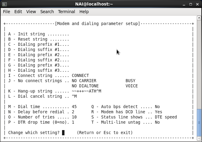
Select ‘Modem and dialing’ in the main configuration menu.
Every setting from A to H should be empty.
Select ‘Exit’ and then Power Cycle the board.
Ethernet Port
Connect the Ethernet port from target board and Host PC to a local network.
Open shell terminal on Host PC and type the following command:
ssh root@<IP address of the target board>
Note
The default IP address of the target board is available on the label or it can be obtained by running the ifconfig command from shell terminal.
Changing the Ethernet IP Addresses
The target board contains 2 Ethernet Interfaces. Each Ethernet Interface is assigned a unique MAC address and static IP address. The MAC addresses and static IP addresses are stored on the motherboard EEPROM. The static IP address can be changed using an EEPROM update utility provided with the unit. The MAC addresses should not be changed.
To access the EEPROM utility from the Linux shell terminal, proceed as follows:
Log in as a root user to the target board. The default password is root.
Display the MBCore version by typing:
naiMBEEPROMUtil version
The following information will display:
root@68arm2-bsp:~# naiMBEEPROMUtil version


===================== MBCore ===================================================
  ExecutionContext:                 Platform ARM-P0 ULTRASCALE+ Master Linux
  Application Built For Target:     68ARM2
  Application Name:                 naiMBEEPROMUtil
  Application Revision:             1.0
  Application Build DateTime:       May 22 2025  10:26:58
  MBCore-Lib Build Revision:        00004.00197
  MBCore-Lib Build Date:            May 22 2025  10:26:55
  NAIBSP Lib Version:               2.23
--------------------------------------------------------------------------------
Then, display the contents of the motherboard EEPROM by typing:
naiMBEEPROMUtil formatteddisplay
The following or something similar (your model may vary) displays:
As you can see, the current Eth-A IPv4Address prints as 192.168.1.16.
As you can see, the current Eth-B IPv4Address prints as 192.168.2.16.
To update the static IP addresses, enter the following commands (substitute your desired IP addresses):
root@68arm2-bsp:~# naiMBEEPROMUtil set EthA_IPv4Address 192.168.1.16

root@68arm2-bsp:~# naiMBEEPROMUtil set EthA_IPv4SubnetMask 255.255.255.0

root@68arm2-bsp:~# naiMBEEPROMUtil set EthB_IPv4Address 192.168.2.16

root@68arm2-bsp:~# naiMBEEPROMUtil set EthB_IPv4SubnetMask 255.255.255.0
The updated IP addresses will take effect on the next system reset.
CAUTION
The naiMBEEPROMUtil program will allow you to erase the entire contents of the EEPROM. DO NOT do this as it will erase important system parameters including the Ether Interface MAC addresses. The ARM board will not function without these settings.
DO NOT alter any of the other EEPROM fields as the ARM board will not function without the correct settings.
Building and Running a Project
Linux
Building and Running a Project
PACKAGE LAYOUT
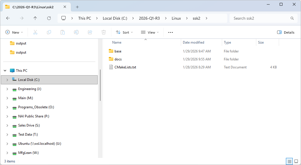
The NAI SSK contains NAI libraries and code to access all onboard and offboard modules. Inside, you’ll find a “base” folder, a “docs” folder, and the root CMakeLists.txt file that’s used as the entry point for CMake to configure a build folder.
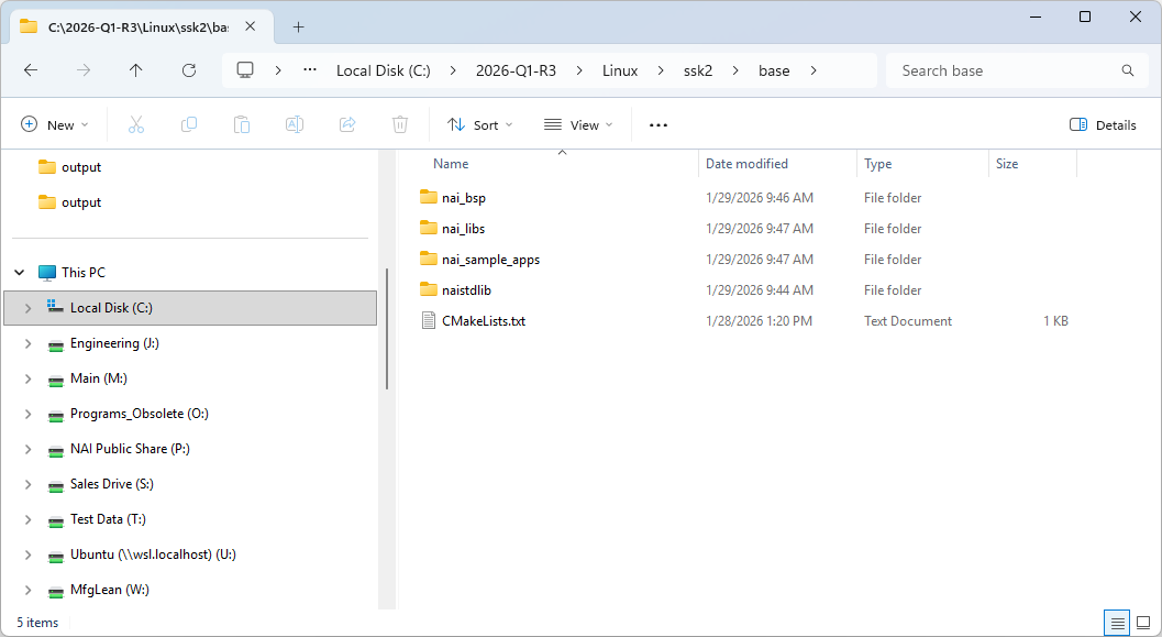
“base” Folder
The base folder contains the all the “C” source code for the SSK.
Project Name
Description (Listed in order of recommended build order)
nai_bsp
Handles OS and processor specific routines, implements interface driver code.
nai_libs
Library routines used by user applications.
nai_sample_apps
Sample applications to demonstrate module functionality.
naistdlib
Additional C libraries.
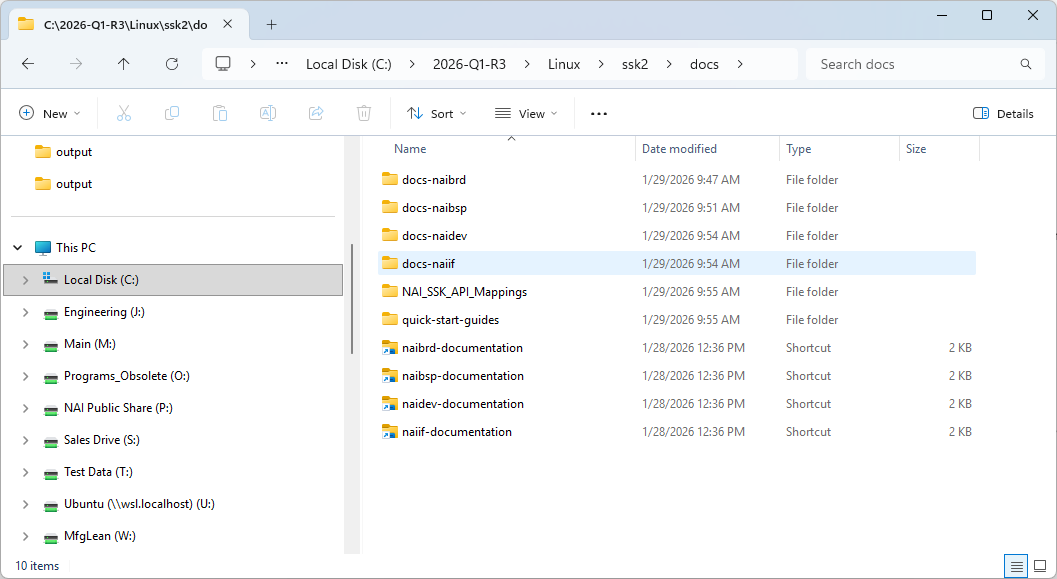
“docs” Folder
The “docs” folder contains local copies of the SSK’s API documentation and quick-start guides that are available on the Docs website.
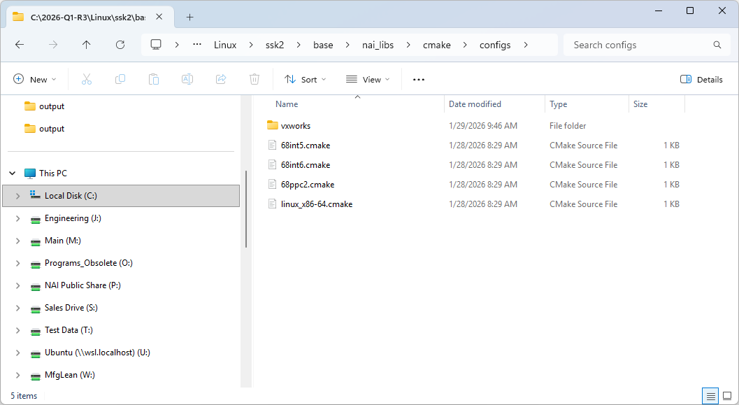
“cmake/configs” Folder
The “cmake/configs” folder exists in the “nai_libs” directory and contains the toolchain files for all supported configurations to be chosen from when generating the build folder with CMake. A generic native Linux host will use the linux_x86-64.cmake toolchain.
CONFIGURING AND BUILDING THE SSK
Instructions
Open the root folder of the SSK in the terminal.
Run the following command with the necessary flags to generate the build folder in the specified location: cmake [flags] -B [build_folder] —toolchain ./cmake/configs/linux_x86-64.cmake
a.
To generate a Release or Debug build, add the flag:
** -DCMAKE_BUILD_TYPE=[Release|Debug]**
b.
To generate shared object (.so) or archive (.a) libraries, add the flag:
** -DBUILD_SHARED_LIBS=[ON|OFF]**
Note
To build for an NAI SBC, replace linux-x86_64.cmake with the toolchain for your board (e.g. 68int6.cmake).
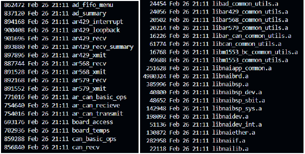
Run the following command to compile the build: cmake —build [build_folder] -j
All compiled binaries and libraries will be found in [build_folder]/bin and [build_folder]/lib, respectively.
Note
In order to change any of the configured flags (switching between .so and .a or Release and Debug), you cannot reuse the same build folder. You must either delete the previously generated build folder or direct CMake to generate a new build folder in a different location. Only then should you rerun the CMake commands with the updated flags.
Example
In this example, the SSK is extracted to “~/nai/ssk/” and the goal is to generate a static, debug build in the folder “build_debug_a”.
Run cd ~/nai/ssk/ to navigate to the root folder of the SSK.
To generate the build folder “build_debug_a” for a static, debug build, use the command: cmake -DBUILD_SHARED_LIBS=OFF -DCMAKE_BUILD_TYPE=Debug -B build_debug_a —toolchain ./cmake/configs/linux-x86-64.cmake
To compile this configuration, run the command: cmake —build build_debug_a -j
All compiled binaries and libraries will be found in build_debug_a/bin and build_debug_a/lib, respectively.
a.
Truncated outputs of ls -l build_debug_a/bin and ls -l build_debug_a/lib
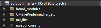
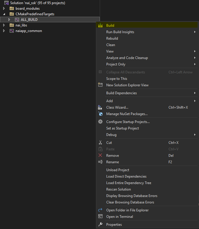
After opening the nai_ssk.sln file in Visual Studio, you should see the following contents in the solution explorer:
To build all libraries and sample applications, expand the CmakePredefinedTargets folder. Right-click on ALL_BUILD and select Build. All sample applications are now ready for execution.
Creating Projects from Scratch
The CMake build process allows for users to create and add new projects to the SSK with minimal configuration. A new project can be created, integrated into the solution file, and linked to all required NAI libraries through two main steps:
Adding a CMakeLists.txt file to the project
Rebuilding the nai_ssk.sln file
To start, navigate to the base/nai_sample_apps/naiapp_src/board_modules directory in File Explorer. This path contains the source code for all sample applications.
For this example, we are going to create a new DSW sample application. Enter the dsw folder and create a new folder named dsw_interrupt_basic.
Enter dsw_interrupt_basic and create another new folder in here named src. This is where you will place your new source file, mimicking the structure of other sample projects.
If you compare your new project to other sample projects such as dsw_basic_ops, you will see that they all have a CMakeLists.txt file in the same directory as their source folder. Copy this file from dsw_basic_ops into the same location of your project and open it in a text editor.
Inside this file, you’ll find that it specifies the project name, some include directories inside the SSK, some link libraries, and an executable name. Other directories or new libraries can be linked here, but for now, replace every instance of the name dsw_basic_ops in the new file with dsw_interrupt_basic. The contents of the file should now look similar to the following:
Once you’ve placed your C/C++ code in the src folder, your project is now ready to build. However, if you reload the solution file, you will see that the new project is still missing from the dsw directory in the Solution Explorer. This is because the contents of your new CMakeLists.txt file has not yet been read and integrated into the ALL_BUILD.vcxproj file. To update this file, you will rebuild the nai_ssk.sln file like you did in Environment Setup.
In a command window, navigate once more to the SSK’s build folder.
Run the following command, entering the Visual Studio version of your choice:
Open the newly-built solution file in Visual Studio. You should now see that your new project can be found in the Solution Explorer, and building the SSK with ALL_BUILD will now include your project.
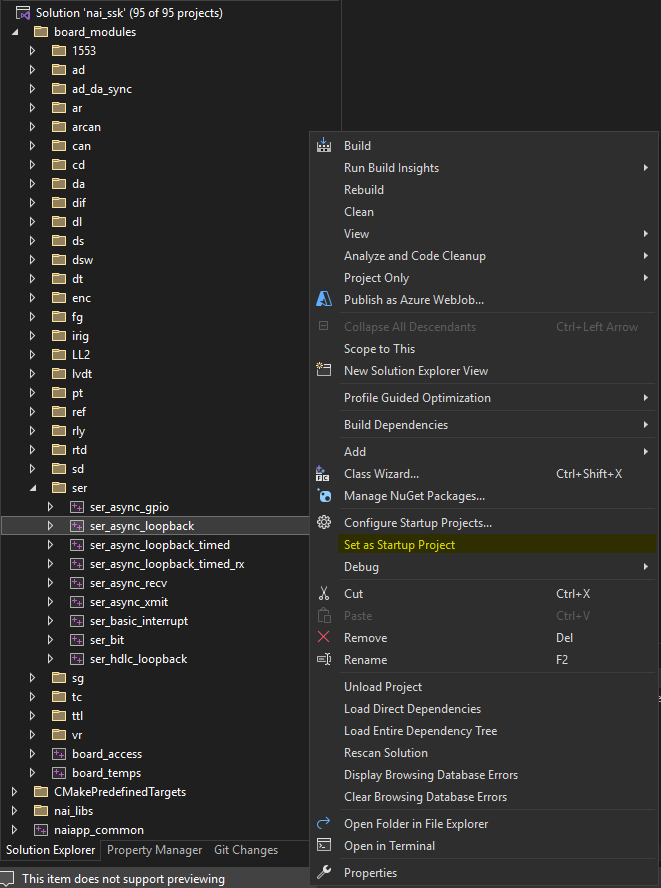
Running a Sample App in Visual Studio
Once all sample applications have been built successfully, they can now be ran from within Visual Studio. From the board_modules folder, select a module family that is included in your hardware. Right-click on a sample application and select Set as Startup Project.
The sample application that you’ve chosen is now configured to run. Select the Local Windows Debugger or Start without Debugging button and a new window will open with the running application. The Windows Library Software Support Kit can be used to run applications that target NAI hardware over ethernet from a Windows host.
If there are already projects when you load the workspace, select them all, right-click, and Delete them. Do NOT select “Delete project contents on disk”.
Import NAI projects by selecting File→Import→Existing Projects into Workspace from the Xilinx SDK toolbar:
Select Next and then select the workspace directory as the root directory:
Select finish to add NAI libraries and sample code projects to the workspace.
If you get this error, simply X it out and X out the Import window.
Your Project Explorer should now look similar to this:
Navigate to Project at the top of Xilinx and make sure Build automatically is unchecked.
Select Window→Preferences from the Xilinx toolbar and set the Indexer to “Use active build configuration” and select OK.
Select all of the projects, right-click, click Build Configurations, Set Active, Debug-UltraScale/Zynq-********** (pick the configuration (Zynq/UltraScale) and the board you have, ex. NIU3A).
Select all of the library projects (nai_bsp projects, nai_libs projects, naiapp_common) and right-click Clean Project then right-click Build Project.
Select a module sample project to Clean then Build which will generate an elf executable that can be run on the processor board.
Creating a New Hello World Application
Navigate to File→New→Application Project to get to the New Project wizard and select Xilinx→Application Project.
Provide a name for the project, select linux as the OS Platform and select psu_cortexa53 as the processor type. Language should default to C and Compiler should default to 64-bit. Press next when complete.
Select the type of application template you’d like to start with and click Finish when complete.
A project with the name entered will appear in the project explorer, right-click the project and build to generate the executable ELF file.
If your projects appear to successfully build but the Project Explorer still shows a red X on them, trying clicking Project→C/C++ Index→Rebuild to rebuild your projects.
Creating Projects from Scratch
Projects can be created with their source code and library includes manually created/linked. This can be helpful if a sample app is having issues and you want to go step by step to make sure nothing is wrong.
If you wish to create projects from scratch (starting from a blank slate, creating projects, and linking the source code manually) then navigate to File→Switch Workpsace and set the path to ‘SSK_Template_FromScratch/Template-petalinux-2018-2/petalinux-appsrc’.
This directory is included with the package and has the same folder structure as the normal petalinux-2018-2 folder but the folders contain nothing so that projects can be made from a blank slate with nothing being detected by Xilinx.
Note
For Zynq, the workspace path would instead be “SSK_Template_FromScratch/Template-petalinux” and all subsequent path locations would follow this path rather than the aforementioned UltraScale one.
Creating an NAI Library Project from Scratch
Navigate to File→New…→Project. Select Library Project under the Xilinx dropdown.
Create a project named nai_bsp-naibsp. Uncheck ‘Use default location’ and change the location to ‘SSK_Template_FromScratch/Template-petalinux-2018-2\petalinux-appsrc\nai_bsp\naibsp’. Select the settings as shown in the screenshot and click Finish when done.
Note
If you use the Brose button to Brose to the location of ‘SSK_Template_FromScratch’ but can’t get to it because the C: drive doesn’t show up as an option to browse to, type ‘C:’ into the Location text box and then press Brose again, and you should be able to Brose into the C: drive.
Your workspace in the IDE should now have an ‘nai_bsp-naibsp’ project.
Click the arrow to expand the project, then right-click on the src folder and click Delete. Press OK after it asks to confirm the deletion.
Right-click the project and click Build Configurations→Manage…
Click New…
Add Debug-UltraScale-68ARM2 as the Name with the Existing configuration based on Debug then press OK.
Note
Replace UltraScale with Zynq if your board is Zynq, and replace 68ARM2 with the board you have, ex. NIU3A, 64ARM1.
Click on this new configuration and click Set Active.
Right-click on the project and select ‘Properties’. Now, select ‘Path and Symbols’ and select the ‘Includes’ page. Click Add… and add the following directories. Press OK when done. If the program asks to rebuild then say no.
Replace the 68arm2 in the config folder with your board, ex. NIU3A, 64ARM1.
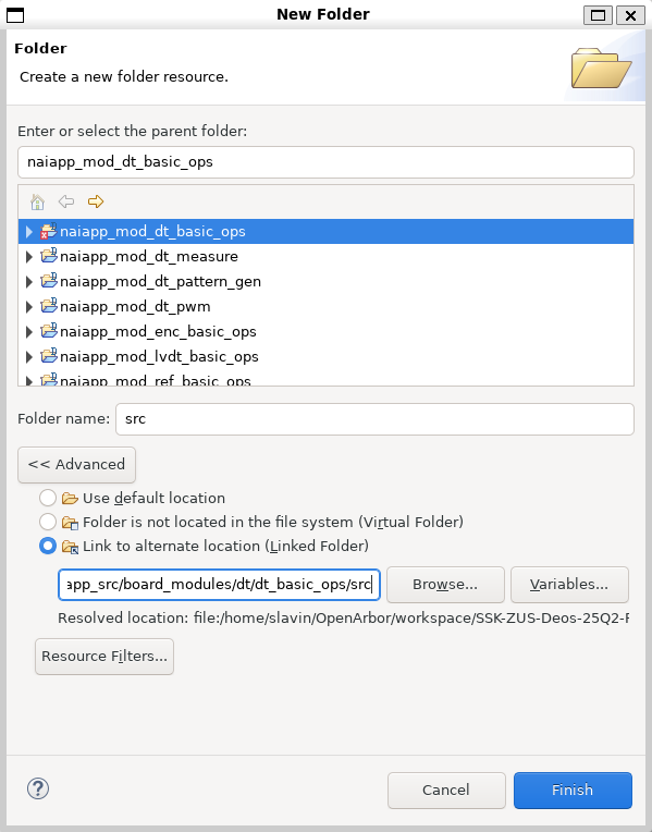
Right-click on the project and select New→Folder.
Click Advanced to show more options then click ‘Link to alternate location (Linked Folder)‘. Write WORKSPACE_LOC…\base\nai_bsp\naibsp as the folder location. Click Finish.
Add another folder with New→Folder. For the path write WORKSPACE_LOC…\base\nai_bsp\naibsp_config_68arm2_petalinux as the folder location. Click Finish.
Note
Replace the 68arm2 in the config file with your board.
Right-click the project to Clean Project and then Build Project. The project should build and the progress will be displayed in the ‘Console’ tab. When finished, there will be a newly created ‘Debug-Zynq/UltraScale-XXXXXX’ folder with an archive file (static library) named ‘libnai_bsp-naibsp.a’.
Adding Additional Library Projects
If other libraries are needed, then the steps are the same except for differences in names and paths. The following is a list of the different library paths, debug configurations, and folder paths.
Note
Replace UltraScale with Zynq if your configuration requires Zynq instead, and replace the 68ARM2 in the Debug Configuration with your board, ex. NIU3A, 64ARM1.
All library projects must be created or imported as described previously in order for the sample apps to build.
Navigate to File→New→Application Project to get to the New Project wizard and select Xilinx→Application Project, then click Next.
Set the project name; in this example, we use naiapp_mod_ad_basic_ops.
Uncheck the use default location check box, and set the location to C:\SSK_Template_FromScratch\Template-petalinux-2018-2\petalinux-appsrc\nai_sample_apps\naiapp_src\board_modules\ad\ad_basic_ops
Note
For Zynq, the workspace path would instead be “SSK_Template_FromScratch/Template-petalinux”, and all subsequent path locations would follow this path rather than the aforementioned UltraScale one.
Change the OS Platform to linux and select psu_cortexa53 as the processor type for UltraScale or ps7_cortexa9 for Zynq. Language should default to C and Compiler should default to 64-bit or 32-bit for Zynq. Press Next when complete.
Under “Available Templates”, select the Linux Empty Application and click the Finish button.
The project “naiapp_mod_ad_basic_ops” should now be added to the Workspace and listed under the Project Explorer. Expand the “naiapp_mod_ad_basic_ops” project and “src” folder and right-click the readme.txt file. Select Delete to remove the readme.txt file from the project. Press OK on the confirmation prompt.
Right-click on the “naiapp_mod_ad_basic_ops” folder and select properties. Select C/C++ General Paths and Symbols and click the Manage Configurations button.
Click the New button to create a new Configuration.
Enter the name as “Debug-UltraScale-68ARM2” or “Debug-Zynq-68ARM2” with the Existing configuration set to Debug and click the OK button. Replace 68ARM2 with the board you want to use.
Select Debug-Zynq/UltraScale-XXXXX and click on the Set Active button to make it the active configuration and click OK to close the window.
In the Configuration drop down box, select the Debug-Zynq/UltraScale-XXXXX configuration if it’s not already selected.
If not already in the Properties window, right-click the project and click Properties→C/C++ General→Paths and Symbols. Under the includes tab, add the following paths:
Replace the 68arm2 in the config file with the board that you have.
Under the Libraries tab click Add… and add the following (ORDER MATTERS):
m
pthread
naiapp_common
nai_libs-naibrd
nai_bsp-naibsp_sys
nai_libs-naiif
nai_libs-naiether
nai_libs-nailib
nai_bsp-naibsp
Under the Library Paths tab click Add…, add the following and check “Is a workspace path” (ORDER MATTERS):
Note
Replace UltraScale with Zynq if your configuration requires Zynq and 68ARM2 with your board, ex. NIU3A, 64ARM1
/nai_bsp-naibsp/Debug-UltraScale-68ARM2
/nai_bsp-naibsp_sys/Debug-UltraScale-68ARM2
/naiapp_common/Debug-UltraScale-68ARM2
/nai_libs-naibrd/Debug-UltraScale-68ARM2
/nai_libs-naiether/Debug-UltraScale-68ARM2
/nai_libs-naiif/Debug-UltraScale-68ARM2
/nai_libs-nailib/Debug-UltraScale-68ARM2
Click OK on the Properties window to save the settings.
In the Project Explorer, right-click on the “naiapp_mod_ad_basic_ops” project and select Build Configurations→Set Active→Debug-Zynq/UltraScale-XXXXX.
To add the source file to the project, right-click on the “src” folder inside the “naiapp_mod_ad_basic_ops” project folder, and select New File. Click the Advanced button followed by the Link to file in the file system check box.
Click the browse button and add the file path SSK_Template_FromScratch\base\nai_sample_apps\naiapp_src\board_modules\ad\ad_basic_ops\src\ad_basic_ops.c. Change the path to WORKSPACE_LOC…\base\nai_sample_apps\naiapp_src\board_modules\ad\ad_basic_ops\src\ad_basic_ops.c if you want the path to be relative to the workspace location. Click the finish button to add the file to the project.
The project is now ready to build by right-clicking the project and clicking Clean Project then right-clicking and clicking Build Project. Once the build completes, an naiapp_mod_ad_basic_ops.elf file will be created in the Debug-UltraScale folder.
Adding Additional NAI Sample App Projects
The steps for adding new sample app projects from scratch are the same steps as stated above but the folder paths depend on the sample app.
The project will be created in a path that starts as SSK_Template_FromScratch\Template-petalinux-2018-2\petalinux-appsrc\nai_sample_apps-naiapp_src\board_modules. The next folder is the module family, followed by the name of the sample app (ex. ad for ad_basic_ops, dt for dt_basic_ops).
Some sample apps include a utils folder which will be seen within the module’s folder. To add these, you right-click the project, click New→Folder→Advanced→Link to alternate location (Linked folder) and Browse… for it.
The source code will be in a path that starts as SSK_Template_FromScratch\base\nai_sample_apps\naiapp_src\board_modules, again followed by the module family, then a folder with the name of the sample app which contains the necessary .c file.
If there are already projects when you load the workspace, select them all, right-click, and select “Delete”. Do NOT select “Delete project contents on disk”.
Navigate to “Window”→”Preferences”. In the Preferences window, navigate to the “Additional”→”C/C++”→“Build”→“Environment” tab.
Create an environment variable named “BOARD” and set the value to the name of the board configuration you wish to build for (e.g. “CIU3”, “NIU3C”, etc.). Then select “Apply and Close”.
Import NAI projects by selecting “File” → “Import” → “Eclipse workspace or zip file” from the toolbar:
Select “Next” and then select the workspace directory as the root directory:
Select “Finish” to add NAI libraries and sample code projects to the workspace.
Your Project Explorer should now look similar to this:
Select “Window"→"Preferences” from the Vitis toolbar and set the Indexer to “Use active build configuration” and select “OK”.
Select “Window"→"Open Perspective” in the Vitis toolbar, and select “C/C++“.
Select the projects that you wish to build, right-click, click “Build Configurations"→"Set Active"→"Debug/Release” depending on the desired build type.
Select all the library projects (nai_bsp projects, nai_libs projects, naiapp_common), right-click, and select “Clean Project”. Then right-click and select “Build Project”.
Select a module sample project to Clean then Build which will generate an elf executable that can be run on the processor board.
Creating a New Hello World Application
Navigate to “File"→"New"→"Other” to get to the New Project wizard and select “C/C++"→"C Project”.
Provide a name for the project, select “Vitis ARM v8 Linux Executable” under “Project type:” and “Vitis ARM v8 GNU/Linux/Toolchain” under “Toolchains”. Then click “Finish” when complete.
A project with the name entered will appear in the project explorer, right-click the project and select New→New Folder. Create a folder named “src” in the resulting window.
Right-click the newly created folder, which should appear under the “helloworld” project. Select New→Source File. In the resulting window, select “Default C source template” and name the file “main.c”.
Open the newly created source file from the project explorer. Inside the source file, add the following lines of code:
Right-click the project and select build to generate the executable ELF file.
Creating Projects from Scratch
Projects can be created with their source code and library includes manually create/linked. This can be helpful if a sample app is having issues and you want to go step by step to make sure nothing is wrong.
If you wish to create projects from scratch (starting from a blank slate, creating projects, and linking the source code manually) then navigate to File→Switch Workspace and set the path to ‘SSK_Template_FromScratch/Template-petalinux-2023-2/petalinux-appsrc’. This directory is included with the package and has the same folder structure as the normal petalinux-202302 folder, but the folders contain nothing so that projects can be made from a blank slate with nothing being detected by Vitis.
Creating an NAI Library Project from Scratch
If not done already, set an environment variable named BOARD to the name of the desired board configuration. Navigate to “Window”→”Preferences”. In the Preferences window, navigate to the “Additional”→”C/C++”→“Build”→“Environment” tab.
Create an environment variable named “BOARD” and set the value to the name of the board configuration you wish to build for (e.g. “CIU3”, “NIU3C”, etc.). Then select “Apply and Close”.
Navigate to File→New…→Other. Select C Project under the C/C++ dropdown.
Select Vitis ARM v8 Linux Executable under Project type. Name the project “nai_bsp-naibsp”. Uncheck ‘Use default location’ and change the location to ‘SSK_Template_FromScratch/Template-petalinux-2023-2\petalinux-appsrc\nai_bsp\naibsp’. Select the settings as shown in the screenshot and click Finish.
Note
If you use the Browse button to Browse to the location of ‘SSK_Template_FromScratch’ but can’t get to it because the C: drive doesn’t show up as an option to browse to, type ‘C:’ into the Location text box and then press Browse again, and you should be able to Browse into the C: drive.
Your workspace in the IDE should now have a project named “nai_bsp-naibsp”.
Right-click on the project and select ‘Properties’. Now, select ‘Paths and Symbols’ and select the ‘Includes’ page. Click Add… and add the following directories. Press OK when done. If the program asks to rebuild then say no.
Click Advanced to show more options then click “Link to alternate location (Linked Folder)“. Write “WORKSPACE_LOC…\base\nai_bsp\naibsp” as the folder location. Click Finish.
Right-click the project to Clean Project and then Build Project. The project should build, and the progress will be displayed in the ‘Console’ tab. When finished, there will be a newly created ‘Debug’ folder with an archive (static library) named ‘libnai_bsp-naibsp.a’.
Adding Additional Library Projects
If other libraries are needed, then the steps are the same except for differences in names and paths. The following is a list of the different library paths, debug configurations, and folder paths.
All library projects must be created or imported as described previously for the sample apps to build.
Navigate to File→New→Other to get to the New Project wizard and select C/C++→C Project, then click Next.
Set the project name. In this example we use “naiapp_mod_ad_basic_ops”.
Uncheck the “use default location” check box, and set the location to C:\SSK_Template_FromScratch\Template-petalinux-2023-2\petalinux-appsrc\nai_sample_apps\naiapp_src\board_modules\ad\ad_basic_ops.
Under “Project type”, select “Vitis ARM v8 Linux Executable” and under “Toolchains”, select “Vitis ARM v8 GNU/Linux Toolchain”. Press “Finish” when complete.
Right-click the project and click “Properties"→"C/C++ General"→"Paths and Symbols”. Under the “Includes” tab, add the following paths:
Under the “Libraries” tab click “Add…” and add the following (ORDER MATTERS):
pthread
m
naiapp_common
nai_libs-naibrd
nai_bsp-naibsp_sys
nai_libs-naiif
nai_libs-naiether
nai_libs-nailib
nai_bsp-naibsp
Under the “Library Paths” tab click “Add…”, then check “Is a workspace path”, and add the following (ORDER MATTERS):
/nai_bsp-naibsp/${config_name:${ProjName}}
/nai_bsp-naibsp_sys/${config_name:${ProjName}}
/naiapp_common/${config_name:${ProjName}}
/nai_libs-naibrd/${config_name:${ProjName}}
/nai_libs-naiether/${config_name:${ProjName}}
/nai_libs-naiif/${config_name:${ProjName}}
/nai_libs-nailib/${config_name:${ProjName}}
Click “Apply” on the “Properties” window to save the settings.
In the Project Explorer, right-click on the “naiapp_mod_ad_basic_ops” project and select “Build Configurations"→"Set Active"→"Debug”.
To add the source files to the project, right-click on the “naiapp_mod_ad_basic_ops” project folder and select “New"→"Folder”. Click the “Advanced” button followed by the “Link to alternate location (Linked Folder)” check box.
Click the browse button and add the following folder path:
Alternatively, enter “WORKSPACE_LOC…\base\nai_sample_apps\naiapp_src\board_modules\ad\ad_basic_ops” if you want the path to be relative to the workspace location.
Click the “Finish” button to add the file to the project.
Select “New Folder” again, and once again select “Advanced”, followed by “Link to alternate location (Linked Folder)”, and add the following foler path:
“WORKSPACE_LOC…\base\nai_sample_apps\naiapp_src\board_modules\ad_ad_common_utils” if you want the path to be relative to the workspace location.
Click the “Finish” button to add the file to the project.
The project is now ready to build. Right-click the project and click Clean Project. Then right-click the project again and select Build Project. Once the build is complete, a file named “naiapp_mod_ad_basic_ops.elf” will be created under the Debug folder.
Adding Additional NAI Sample Projects
The steps for adding new sample app projects from scratch are the same steps as stated above but the folder paths depend on the sample app.
The project will be created in a path that starts with ‘SSK_Template_FromScratch\Template-petalinux-2023-2\petalinux-appsrc\nai_sample_apps\naiapp_src\board_modules’. The next folder is the module family followed by the name of the sample app (ex. ad\ad_basic_ops, dt\dt_basic_ops).
Some sample apps include a utils folder which will be seen within the module’s folder. To add these, you right-click the project, click New→Folder→Advance>>→Link to alternate location (Linked folder) and Browse… for it.
The source code will be in a path that starts as ‘SSK_Template_FromScratch\base\nai_sample_apps\naiapp_src\board_modules’ with the next folder being the module family followed again by the name of the sample app, which contains the necessary .c file.
Debugging a Sample App on Vitis
We will be copying one of the built .elf sample apps to the target board’s home/root folder. You can do this in any preferred way, but the following steps shouw how to do it using Vitis.
Go to the “Remote System Explorer” perspective in the top right. If you don’t have this then in the top tab click “Window"→"Perspective"→"Open Perspective"→"Other” and double click “Remote System Explorer”.
Right-click the blank area and click “New"→"Connection…“. There are several modes of connection. In this case, “SSH Only” with the IP address of the board is being used.
Navigate to Root/home/root. Enter the username “root” and the password “root”. Right-click the root and click “Export from Project”.
In the “Remote file system” page, navigate to the sample app you want. On the left side click the dropdown arrow to expand it, then click the “Debug” folder. Then on the right, check the .elf file. When you are done, click Finish.
Run the sample app on Teraterm to make sure the app is working and to give execute permissions to it. You can also just use Teraterm as a simple way to use the program.
Navigate to /home/root/ on the terminal:
# cd /home/root/
Give Execute permission to the application:
# chmod 777 <Sample Application>
Execute program from Linux shell terminal:
# ./<Sample Application>
In Vitis with the sample app selected in the “Project Explorer”, navigate to “Debug As"→"Debug Configurations…“.
Note
The same steps work for “Run As"→"Run Configurations…” if you prefer to use Vitis to run the program.
In the “Debug Configurations” window, double click “Target Communication Framework”, select the new configuration, uncheck “Use local host as the target”, click on the TCF Agent and click Apply.
Navigate to the “Application” tab. The local file path should be entered as “Debug/<sample_app>.elf”. The remote file path should be filled in as “home/root/<sample_app.elf>“. Click Debug when finished.
Vitis should ask to open the Debugger perspective.
The following guide uses the NIU3A as an example. Replace NIU3A in the instructions with the name of your board where applicable, eg. 68ARM2. If you are using an Intel-based board, eg. 68INT6, please check your software package or contact NAI for alternative instructions.
NIU3A BSP
This section will cover the installation of the NIU3A BSP and the creation of a VxWorks Source Build project.
Install NIU3A BSP
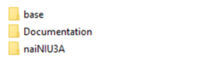
The first step in configuring the NAI VxWorks 7 BSP is to copy the BSP files to the appropriate directory. The supplied BSP folder is named naiNIU3A:
The base folder contains the NAI Library and its BSP files, along with the source of the samples for the NIU3A and its functions modules. The documentation folder contains the NAI Library documentation for each function call in the SSK.
Once the naiNIU3A BSP has been located, copy the folder in the following directory:
For VxWorks 7 SR660:
$(WIND_BASE)/pkgs_v2/os/board/xilinx/
For VxWorks 7 (22.09 - 24.03):
$(WIND_BASE)/source/os/arch/arm/board/Xilinx/
Create Source Code Build
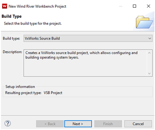
Now with the NIU3A BSP source copied into the appropriate directory a VSB project can be created. Open Workbench and select File → New → Wind River Workbench Project. Under Built Type select VxWorks Source Build and click the Next> button.
Note
Screenshots may differ based on version of VxWorks/Workbench being used.
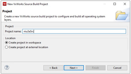
Give the VxWorks Source Build project a name and click the Next> button.
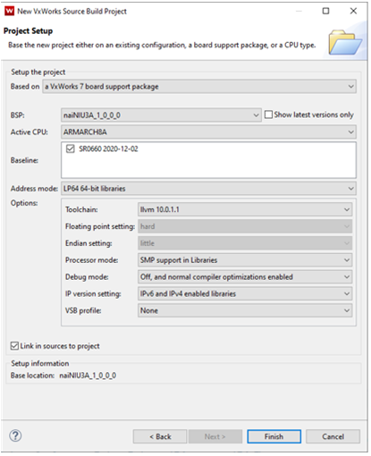
In the next window, base the VSB on a VxWorks 7 board support package, and the BSP as naiNIU3A_1_0_0_0 as the fill in options. Click Link in sources to project check box if you want all VxWorks kernel source copied to your project. Click the Finish button to complete the project creation.
Note
Screenshots may differ based on version of VxWorks/Workbench being used.
Once the Project Setup Window finishes creating the project (window closes), right-click on VSB project and select Build Project.
Once the VSB has been built, projects for NAI BSP / NAI BRD, and VIP can be created.
PROJECT CREATION
In this section we will cover the creation of the VxWorks image project, and a downloadable kernel module project for the NAIBRD, NAI BSP and the sample applications. NAI BSP is a collection of drivers to interface to NAI hardware and VxWorks 7. In the BSP that was installed earlier is an archive of NAI BSP object code.
Create a VxWorks Image Project
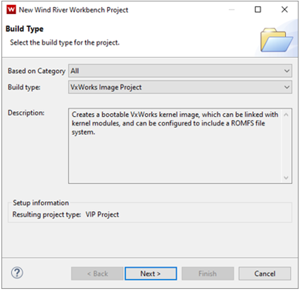
Create new VxWorks image project by selecting File → New → Wind River Workbench Project. Under Build Type select VxWorks image project and click Next>.
Note
Screenshots may differ based on version of VxWorks/Workbench being used.
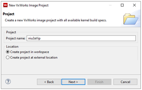
Give VxWorks Image Project at name and click Next>.
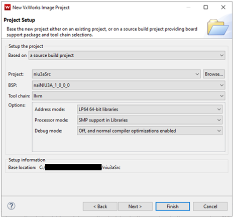
Base the VxWorks Image Project on source build project you built earlier. Make sure BSP and source project name is correct, then click Next>.
Note
Screenshots may differ based on version of VxWorks/Workbench being used.
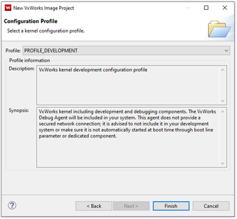
It is recommended to use PROFILE_DEVELOPMENT when creating a project in a development phase. Click Finish to complete the project creation process.
Note
Screenshots may differ based on version of VxWorks/Workbench being used.
VIP Kernel Configuration
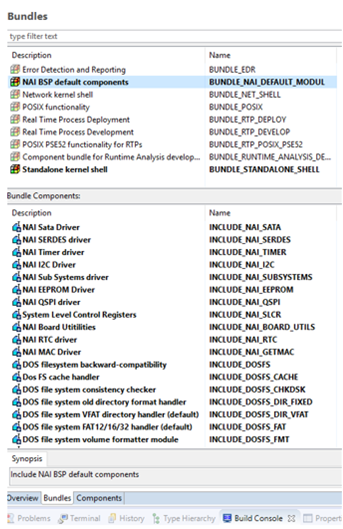
After Workbench creates the VIP, double click Kernel Configuration in the project. For convenience under the Bundles tab there is NAI BSP default components.
Add the NAI BSP default components bundle to include the NAI BSP in entirety. Standalone kernel shell adds useful components for development as well.
Note
Screenshots may differ based on version of VxWorks/Workbench being used.
At this point we need to create a DKM of NAIBRD and the NAI_BSP before continuing onto building the niu3aVip.
DKM For NAIBSP and NAIBRD
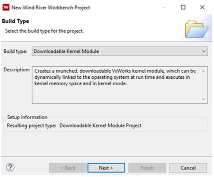
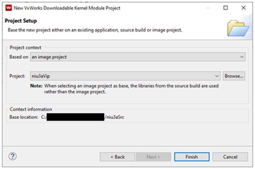
Create a Downloadable Kernel Module project by clicking on File → New → Wind River Workbench Project then click Next>.
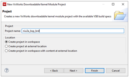
Give project at name, then click Next>.
Note
Screenshots may differ based on version of VxWorks/Workbench being used.
Base project on VxWorks image project (niu3aVip), click Finish.
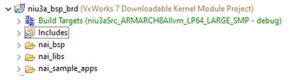
Delete dkm.c that was automatically created and add the nai_bsp, nai_libs and nai_sample_apps folders (located in the base folder) into DKM project.
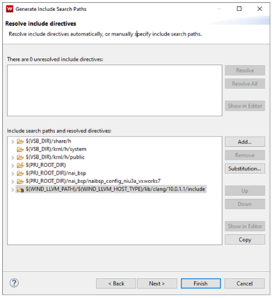
Right-click on DKM project and select Rebuild Project. If this is the first time this project is built you will be prompted to Generate the include paths. Generate the includes by clicking the Generate Includes… button, followed by the Next> button.
To resolve include paths, add the following paths to the DKM project:
$(PRJ_ROOT_DIR)
$(PRJ_ROOT_DIR)/nai_bsp
$(PRJ_ROOT_DIR)/nai_bsp/naibsp_config_niu3a_vxworks7
Note
Screenshots may differ based on version of VxWorks/Workbench being used.
Click Finish and build NAI BSP, NAI Library and samples (NAIBRD) DKM project.
Add NAI BSP Project to VIP
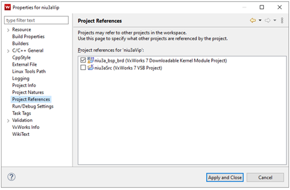
Now that the niu3a_bsp_brd project has been completed we will need to switch back to the niu3aVip project. Add the niu3a_bsp_brd project as a project reference to the niu3aVip by right-clicking on niu3aVip project and selecting Properties. Next, select Project Reference and click on the check box for the niu3a_naibsp project. Click on Apply and Close.
Note
Screenshots may differ based on version of VxWorks/Workbench being used.
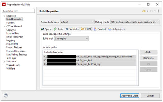
Configure VIP Paths
In niu3aVip VxWorks Image Project right-click on project, click Properties followed by Build Properties then select the Paths tab. Add the three paths below referencing the niu3a_bsp_brd project:
*replace <PATH_TO_NIU3A_BSP_BRD_PROJECT> with actual path to project.
Click the Apply and Close button.
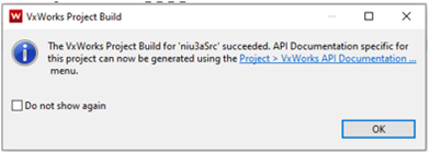
Right-click on niu3aVip project and select Rebuild Project to build the kernel image. At this point the kernel image should be built successfully and is ready to be loaded onto the NIU3A.
BOOTING VXWORKS 7 KERNEL WITH UBOOT
This section will cover booting the newly created VxWorks image file over uboot. There are sections for loading the image via tftp, and from SATA on the NIU3A.
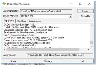
TFTP Booting VxWorks
Start a tftp server on host PC. For windows $(WIND_BASE)/host/x86-win32/bin/ tftpd32.exe and browse to directory that contains uVxWorks and naiNIU3A.dtb files.
Note
Screenshots may differ based on version of VxWorks/Workbench being used.
Stop Uboot on the NIU3A by pressing the esc key. Once at the uboot prompt, modify the uboot environment variables to reflect your environment. The VxWorks kernel during boot up will read bootargs variable to get host, target, network mask, as well as username and password for FTP server running on host.
To boot VxWorks kernel over network: ZynqMP> tftpboot 0x05000000 uVxWorks ZynqMP> tftpboot 0x04000000 naiNIU3A.dtb ZynqMP> run R5fw && run load_cal && run bmargs && run vxargs ZynqMP> bootm 0x05000000 - 0x04000000
To automate booting over the network: ZynqMP> setenv vxBootTftp tftpboot 0x05000000 uVxWorks;tftpboot 0x04000000 naiNIU3A.dtb;bootm 0x05000000 - 0x04000000 ZynqMP> setenv load_fw_vx_tftp echo Loading VxWorks from TFTP… && run R5fw && run load_cal && run vxargs && run vxBootTftp ZynqMP> setenv bootcmd run load_fw_vx_tftp ZynqMP> saveenv
On next power cycle of target VxWorks should boot over network automatically.
Booting VxWorks from SATA
The NIU3A supports booting the VxWorks image directly from SATA. Uboot requires a tftp connection to the NIU3A in order to configure the NIU3A to boot a VxWorks image from SATA. Once a tftp connection has been established load the uVxWorks and nai68arm2.dtb file and boot VxWorks on the NIU3A. For more information on booting over tftp, see section “Error! Reference source not found.”.
Write a VxWorks image to SATA and boot image in UBoot
UBoot will need a FAT32 filesystem to boot a VxWorks kernel. After booting VxWorks over a network, retrieve the name of SATA device on the NIU3A, by entering the command ‘devs’. In the example below, the SATA name is “/ata0a”.
To write to the SATA on NIU3A, the SATA write protection must be disabled. Enter the following at the VxWorks command line:
→ naiSetSataWriteProtect 0
Then to format for FAT32: → dosFsVolFormat “/ata0a”,0x20
Formatting /ata0a for DOSFS
Instantiating /ata0a as rawFs, device = 0x20001
Formatting…Retrieved old volume params with %100 confidence:
Volume Parameters: FAT type: FAT32, sectors per cluster 64
2 FAT copies, 0 clusters, 10069 sectors per FAT
Sectors reserved 32, hidden 63, FAT sectors 20138
Root dir entries 0, sysId (null), serial number c500000
Label:” ” …
Disk with 82477647 sectors of 512 bytes will be formatted with:
Volume Parameters: FAT type: FAT32, sectors per cluster 64
2 FAT copies, 1288398 clusters, 10069 sectors per FAT
Sectors reserved 32, hidden 63, FAT sectors 20138
Root dir entries 0, sysId VX5DOS32, serial number c500000
Label:” ” …
OK.
Once the SATA has been formatted copy your naiNIU3A.dtb and uVxWorks to the SATA drive
→ cp “naiNIU3A.dtb”,“/ata0a”
copying file naiNIU3A.dtb → /ata0a/ naiNIU#A.dtb
value = 0 = 0x0 → cp “uVxWorks”,“/ata0a”
copying file uVxWorks → /ata0a/uVxWorks
Once the naiNIU3A.dtb and uVxWorks have been copied to SATA, the NIU3A can be power cycled to configure Uboot.
Stop Uboot on the NIU3A by pressing the Esc key. Once at the uboot prompt, modify the uboot environment variables to reflect your environment.
The NAI SSK contains NAI libraries and code to access all onboard and offboard modules. The SSK contains two folders, one labeled base which contains the NAI libraries and another labeled deos_kismet. This folder contains fully configured workspace containing project files that link to the source code in the base folder for Deos RMA. Below is an overview of the projects available in the deos_kismet folder.
Project Name
Description (Listed in recommended build order)
naibsp
Handles OS and processor-specific routines, implements interface driver code
nailib
Defines common utility routines used by other NAI libraries
naiether
Defines NAI ethernet protocol to handle NAI commands over ethernet
Defines NAI routines used by NAI sample applications
naiapp_common
Defines utility routines used by NAI sample applications
naiapp_mod_*
NAI sample application programs for all available modules
nai-ultrascale
Deos platform project used to build hyperstart/composite image for NAI 68ARM2, NIU3A, and NIU3E
Building Deos BSP Package in OpenArbor
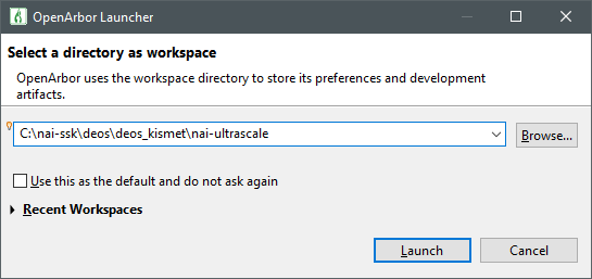
Launch OpenArbor
Select the deos/deos_kismet/nai-ultrascale directory in the location of the SSK
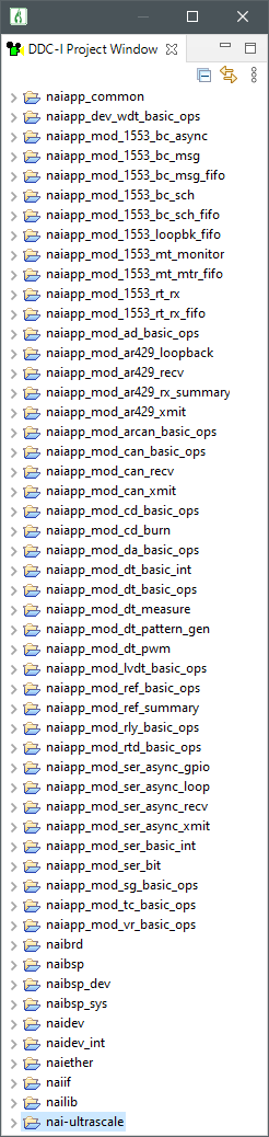
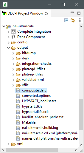
Once the workspace has been selected, the following projects should be made available to build in the DDCI-Project Window. (Projects may vary depending on system configuration)
Building the nai-ultrascale platform project will generate a composite.darc file which contains the kernel, configuration files and application code that will be loaded onto the target system
Refer to the file uboot_env_vars.md for U-Boot environment variables that need to be set to net-boot Deos on a given platform
Running Other Sample Applications in OpenArbor
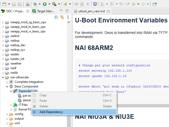
By default, the only dependency that the nai-ultrascale platform project has is the Deos standard-apps which enable network connection to run tools like the Video Stream and Status Monitor. To run any of the included NAI sample applications, you can add the application as a dependency on the platform project. The Deos image needs to be rebuilt and reloaded.
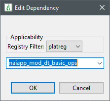
Go to the platform project nai-ultrascale and navigate to Deos Component → Dependencies. Right-click and select Add Dependency
Select the application you would like to integrate with the nai-ultrascale BSP
Build all projects
In the Target Manager add a connection for the nai-ultrascale platform project
Launch the Status Monitor or the Video Stream
Right-click the Status Monitor or Video Stream and click Update Target Load. Make sure End up in registry is set to platreg if that is where application dependency is. Make sure Force Cold Start is checked
Deos should now cold start and the new application should be running
Changing Board IP Address
Change the IP address in u-boot via the ipaddr environment variable. Make sure to save the environment via the saveenv command:
OpenArbor stores information about the platform’s IP address in the lwip.config file.
Navigate to the platform project nai-ultrascale → config → lwip.config
Change the IP address on the following line:
interface=xilinx-gem:0 192.168.1.16 255.255.255.0
More information can be found in the Deos NAI-UltraScale BSP User Guide.
Speeding Up the Platform Build
To speed up builds and avoid building libraries that should not need to be modified during application development, we can follow a couple steps to point Open Arbor to the location of our built binaries.
Open OpenArbor and build all NAI libraries
Open a Windows PowerShell instance and run the script named release-me.ps1 with the following arguments
./release-me.ps1 -copyBinaries:$true
This will copy the parts of the “desk tree” in the output directory to a common location that OpenArbor can be pointed to look at
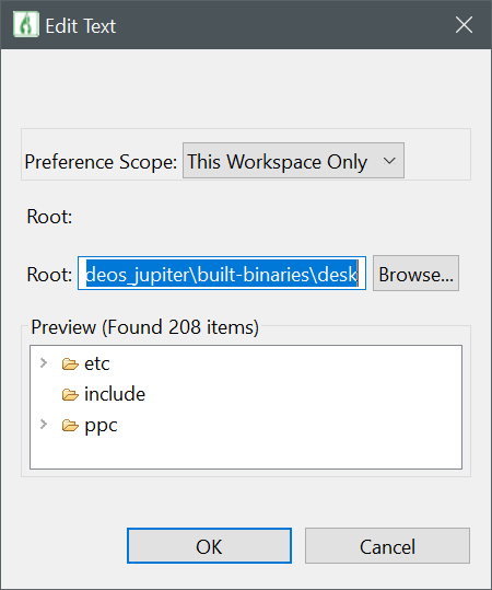
In OpenArbor navigate to Window → Preferences → DDC-I → Deos Search Path
Click ‘Add’. Change Preference Scope to This Workspace Only and browse to the path that the Power Shell script created:
/SSK/deos/deos_kismet/$NAI_Board_Name/built-binaries/desk
Hit OK
Now, if you would like to skip building the NAI libraries you can “Close Project” on any applicable libraries that have been copied. OpenArbor will check the search path to see if it has binaries for those libraries and use them instead
If you need to debug any NAI libraries or want to navigate source, open up the projects
Deos 653
By default, the naibsp library is configured to be used by a Deos RMA process. If the user would like to call the library from a Deos 653 process, the following changes must be made so that naibsp can use the correst Deos Semaphore implementation:
In the naibsp project, navigate to Deos Component→Dependencies and add deos-653-p1 as a dependency.
In the naibsp project properties, navigate to DDC-I Options→C Compile→Preprocessor and add a Defined Macro named DEOS653P1. If the application is a C\++ application, the same change will need to be made in the C++ Compile tab.
Creating Projects from Scratch
These steps also demonstrate the process for how to link NAI libraries to your own application the same way that they are referenced in the sample applications. Several of these libraries are required for communication with NAI hardware.
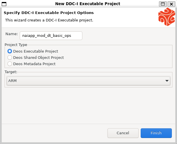
Navigate to File→New→DDC-I Executable Project.
In the New DDC-I Executable Project window, enter a project name. Select Deos Executable Project as the Project Type and the architecture of your board in the Target dropdown.
Note
This guide is targeting the nai-ultrascale platform, so ARM Target is selected. Your board may require you to select Power PC or x86_64.
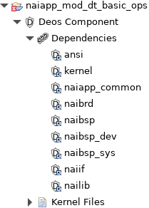
Expand the new project in the DDC-I Project Window, and open the Deos Component→Dependencies tabs.
Modify the platform project’s .options file to add the following dependencies:
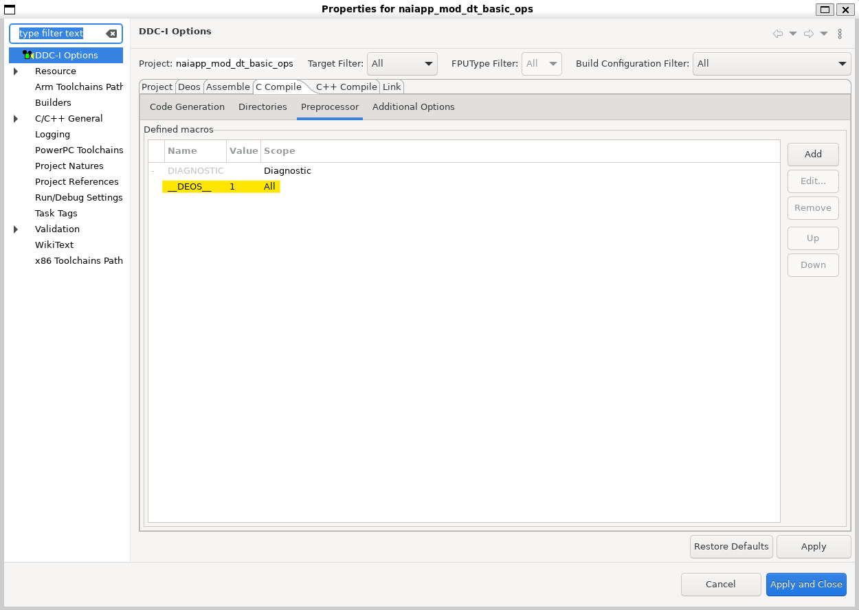
Switch over to the Preprocessor tab under C Compile. Add a new Defined Macro named \DEOS with a value of 1.
Note
If the application is a C\++ application, the same change will need to be made in the C++ Compile tab.
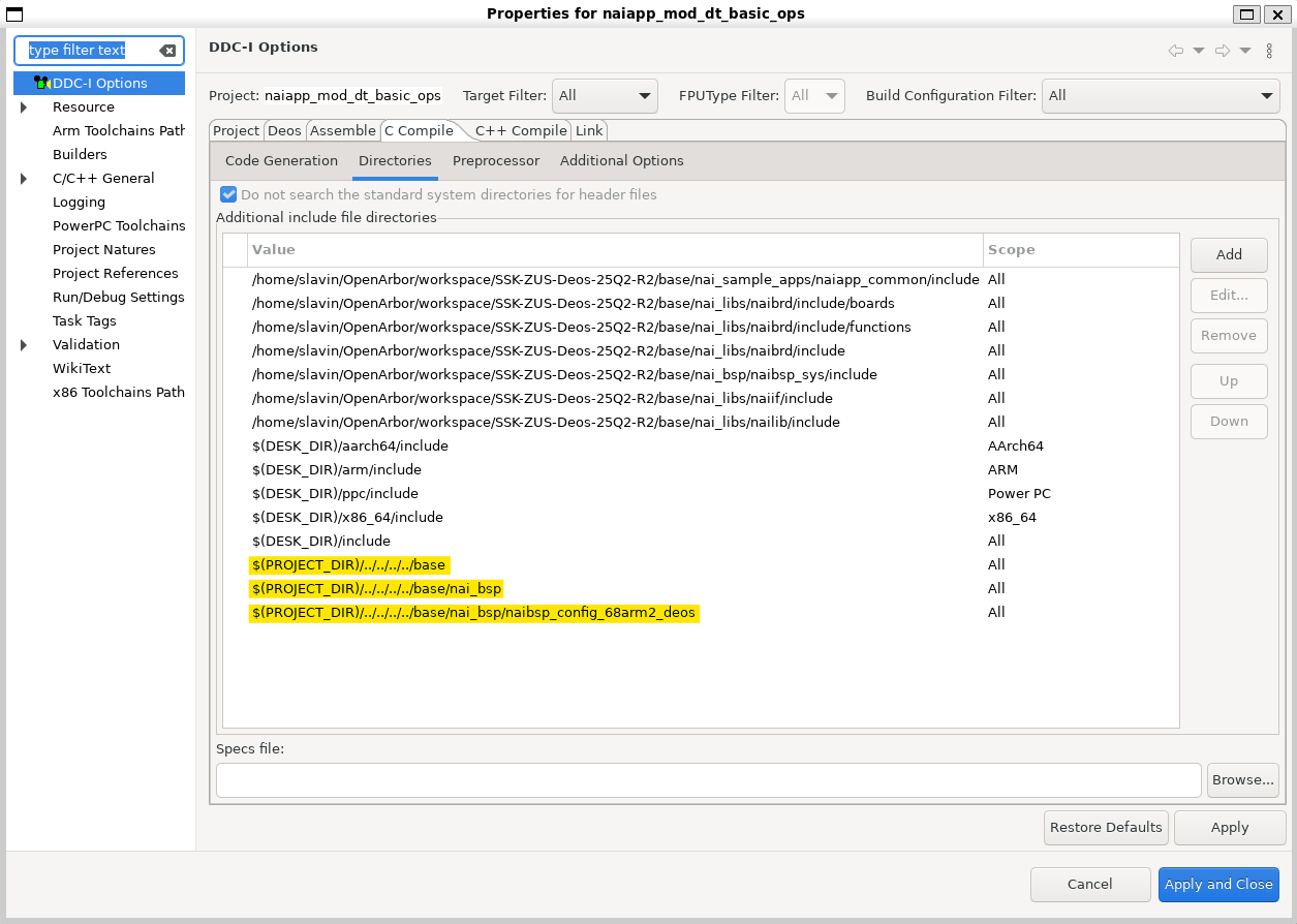
To add a source folder to the project, right-click the project and select New→Folder→Advanced.
Select Link to alternate location (Linked Folder) and Browse to the directory of your src folder. Source files for sample applications are located at base/nai_sample_apps/naiapp_src/board_modules/{MOD_NAME}/{PROJECT_NAME}.
Deos Executable Projects use a process developer XML file to define which process, threads, mutexes, and other resources are allocated to them. You have two options for how to create one for your project:
.. If you are already familiar with process developer xml files and/or aware of which resources you are going to allocate, navigate to File→New→Other→DDC-I→DDC-I Deos Process Developer XML File and use the XML wizard to define your resources.
.. If you are not familiar with process developer xml files or are not sure of which resources are required by naibsp, copy the “xml” folder and included pd.xml file from a project in the same module family and paste it in your project directory. Change the names in the xml file referencing the other project to the name of your project.
The naibsp project contains a naibsp-resources.pia.xml file which
adds memory mapped resources to the integration. Below is a description of what
these resources are:
Resource
Description
DMABuffer1
Used by NAI’s DMA engine, write data to DMA here, or read DMA data from here
ModuleInfo
NAI internal use. Needed by naibsp
ModuleConfigStatus
NAI internal use. Needed by naibsp
MotherboardCommon
NAI internal use. Needed by naibsp
ModuleControl
NAI internal use. Needed by naibsp
TTLSync
Provides access to 68ARM2 TTL Sync Engine
ModuleSpace
NAI internal use. Needed by naibsp
PCI[1-5]Mem
PCIe BAR for endpoint cards and their modules
ZynqMPCore
UltraScale+ memory regions. Refer to Xilinx UG1087
uart_zus[0,1]
UART UltraScale+ memory regions. Refer to Xilinx UG1087
i2c_zus[0,1]
I2C UltraScale+ memory regions. Refer to Xilinx UG1087
rtc
Real-time-clock UltraScale+ memory regions. Refer to Xilinx UG1087
SWDT_LPD
System Watchdog Timer UltraScale+ memory region. Refer to Xilinx UG1087
SystemTimestampGeneratorSecure
System Timestamp Generator UltraScale+ memory regions. Refer to Xilinx UG1087
SysMon
PL System Monitor UltraScale+ memory regions. Refer to Xilinx UG1087
PSUCSU
PMU Configuration Security Unit UltraScale+ memory regions. Refer to Xilinx UG1087
Some of these memory mapped resources are required for a project to communicate with NAI hardware, while others are only necessary for utilizing certain functionality (e.g. DMABuffer1). These are included in the process developer xml files for the sample applications. If you are creating your own pd.xml file, be sure to add these resources by using the sample applications as a template.
Configuring Interrupts
For systems using NAI interrupts, the naibsp_sys-attach-interrupt
feature must be enabled. This creates an ISR thread when naibrd_ConnectISR() is called. It
increases the thread quota, creates a thread template, and assigns ownership to
the responsible interrupt.
To enable it, add the following to your process developer XML file:
<usedFeatureSet name = "naibsp_sys" versionRequirement = "none" versionNumber = "none" featureSetUndefinedAction = "error" > <usedFeature name = "naibsp_sys-attach-interrupt" > <usedFeatureParameter name = "nameOfScheduler" value = "default-core-0" ></usedFeatureParameter> <usedFeatureParameter name = "nameOfUsingProcessInstance" value = "dt_basic_interrupt_process" ></usedFeatureParameter> </usedFeature></usedFeatureSet>
Add your project as a dependency in the nai-ultrascale project as outlined in Step 3. Right-click the project and select Rebuild Project.
If you do not want to use your host pc terminal and
would like to run an application you have loaded onto your single board computer, NAI SIU, or NAI NIU follow this guide.
Link to original
Link to original

/../../dev-guides/images/pl1.png)
/../../dev-guides/images/pl2.png)
/../../dev-guides/images/pl3.png)
/../../dev-guides/images/pl4.png)
/../../dev-guides/images/pl5.png)
/../../dev-guides/images/pl6.png)
/../../dev-guides/images/pl7.png)
/../../dev-guides/images/pl8.png)
/../../dev-guides/images/pl9.png)
/../../dev-guides/images/pl10.png)
/../../dev-guides/images/pl12.png)
/../../dev-guides/images/pl13.png)
/../../dev-guides/images/pl14.png)
/../../dev-guides/images/pl15.png)
/../../dev-guides/images/pl16.png)
/../../dev-guides/images/pl17.png)
/../../dev-guides/images/pl18.png)
/../../dev-guides/images/pl19.png)
/../../dev-guides/images/pl20.png)
/../../dev-guides/images/pl21.png)
/../../dev-guides/images/pl22.png)
/../../dev-guides/images/pl23.png)
/../../dev-guides/images/pl24.png)
/../../dev-guides/images/pl25.png)
/../../dev-guides/images/pl26.png)
/../../dev-guides/images/pl27.png)
/../../dev-guides/images/pl28.png)
/../../dev-guides/images/pl29.png)
/../../dev-guides/images/pl30.png)
/../../dev-guides/images/pl31.png)
/../../dev-guides/images/pl32.png)
/../../dev-guides/images/pl33.png)
/../../dev-guides/images/pl34.png)
/../../dev-guides/images/pl35.png)
/../../dev-guides/images/pl36.png)
/../../dev-guides/images/pl37.png)
/../../dev-guides/images/pl38.png)
/../../dev-guides/images/pl2023_1.png)
/../../dev-guides/images/pl2023_2.png)
/../../dev-guides/images/pl2023_3.png)
/../../dev-guides/images/pl2023_4.png)
/../../dev-guides/images/pl2023_5.png)
/../../dev-guides/images/pl2023_6.png)
/../../dev-guides/images/pl2023_7.png)
/../../dev-guides/images/pl2023_8.png)
/../../dev-guides/images/pl2023_9.png)
/../../dev-guides/images/pl2023_10.png)
/../../dev-guides/images/pl2023_11.png)
/../../dev-guides/images/pl2023_13.png)
/../../dev-guides/images/pl2023_14.png)
/../../dev-guides/images/pl2023_15.png)
/../../dev-guides/images/pl2023_16.png)
/../../dev-guides/images/pl2023_17.png)
/../../dev-guides/images/pl2023_18.png)
/../../dev-guides/images/pl2023_19.png)
/../../dev-guides/images/pl2023_20.png)
/../../dev-guides/images/pl2023_21.png)
/../../dev-guides/images/pl2023_22.png)
/../../dev-guides/images/pl2023_23.png)
/../../dev-guides/images/pl2023_24.png)
/../../dev-guides/images/pl2023_25.png)
/../../dev-guides/images/pl2023_26.png)
/../../dev-guides/images/pl2023_27.png)
/../../dev-guides/images/pl2023_28.png)
/../../dev-guides/images/pl2023_29.png)
/../../dev-guides/images/pl2023_30.png)
/../../dev-guides/images/pl2023_31.png)
/../../dev-guides/images/pl2023_32.png)
/../../dev-guides/images/pl2023_33.png)
/../../dev-guides/images/pl2023_34.png)
/../../dev-guides/images/pl2023_35.png)
/../../dev-guides/images/pl2023_36.png)
/../../dev-guides/images/pl2023_37.png)
/../../dev-guides/images/pl2023_38.png)
/../../dev-guides/images/pl2023_39.png)
Link to original