Watchdog Timers
Edit this on GitLab
Overview
What is a Watchdog Timer
A Watchdog Timer (WDT) is a failsafe mechanism used in devices to turn off or reset the device if an error within it occurs. WDTs are important as they can reset a device during a fault in hardware or a stall in software, thus maintaining the device. WDTs also do not need humans around to reset a device, saving time and money.
How do WDTs Work
Once a WDT in a device is enabled, the watchdog can detect errors in by receiving routine signals sent by the device, and if the device is late in sending one, potentially due to a stall or error in the system, the WDT detects this and gets triggered.
Different WDTs have different methods for analyzing signals and concluding whether or not a signal was 'late' and therefore if the system is functioning properly. For example, some WDTs implement 'windows' that clearly dictate when a signal should be received and others use a simple countdown method where a signal must be received before a countdown reaches 0.
However, WDTs all serve the purpose of reseting or disabling a device when an error occurs.
Feature Applications
WDTs can be used in many places for many things ranging from commercial to defensive applications. Because of their importance in preventing system failures, WDTs are used commercially in:
-
Networks
-
Transportation
-
Consumer Electronics
Meanwhile, because WDTs can automatically reset a device such that humans do not need to be near it, they can be used in defense applications like:
-
Satellites
-
Avionic Systems
NAI’s Watchdog Timers
NAI produces both motherboards and modules that have watchdog timers, but these timers use different methods for determining when a fault occurs in the system.
Motherboard WDT
NAI’s motherboards implement a 'countdown' method for determining when to trigger the WDT. In other words, the WDT will have a timer that is counting down to 0, such that when the timer ends, the WDT will be triggered and the board gets reset. To prevent the timer from reaching 0, the motherboard is responsible for sending routine signals which will reset the timer, restarting the countdown.
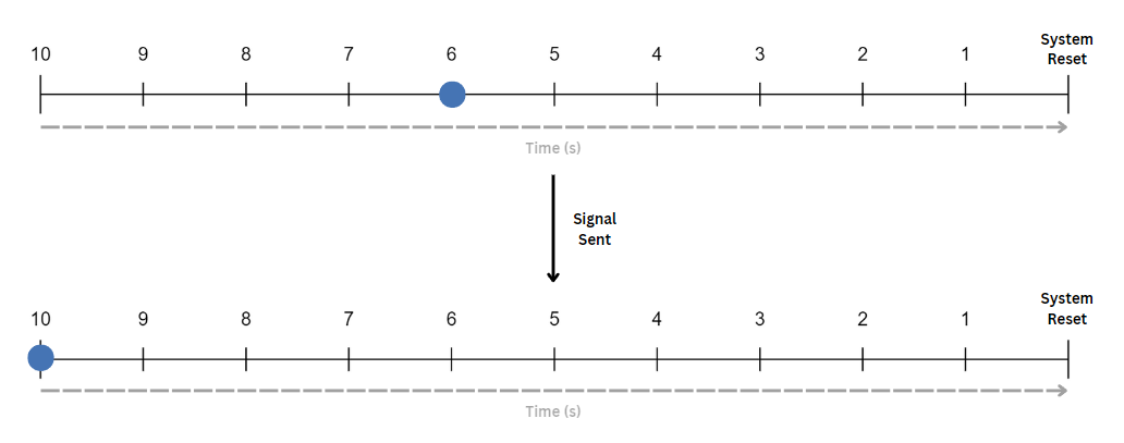
Should a signal not be sent in time, the countdown will reach 0 and the WDT sends a message to the board to reset itself. This method is more flexible for the signals sent.
Module WDT
Some NAI modules like DT4 implement their own version of a WDT that will reset the module upon any error. These modules implement a window system that dictates when a signal should be sent to the WDT. Should signals be sent too late, too early, or too frequently, the WDT will be triggered.
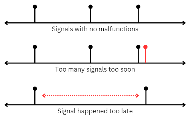
These 'windows' that determine when a signal is late or early are called Quiet Time and Open Window. The programmer is able to configure these windows.
The rules of these windows are as followed:
-
No signals are allowed in Quiet Time
-
Exactly one signal must be received in Open Window
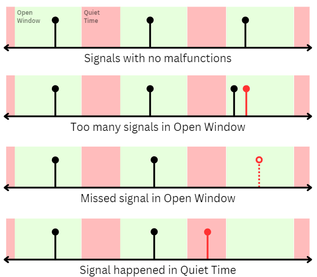
While this method may be more complex, it provides stricter rules on when a signal should be sent, allowing for higher detection of any faults within the module.
Getting Started
You can use the watchdog timer available on both the motherboard and the module for your purposes, but handling each of them has different steps and requirements. After setting up either the module or motherboard, you can configure the WDTs on either of them.
Use Case 1 - Handling the Module Watchdog Timer
In this example, we are going to hook up a module and experiment with the WDT by inputting values for our Quiet Time and Open Window and see how a signal gets received depending on these values.
Hardware Setup
To hook up a module, you will need:
-
A module with a built-in WDT
-
A compatible board
-
A power source
-
An ethernet cable (or another way to connect the board to your PC)
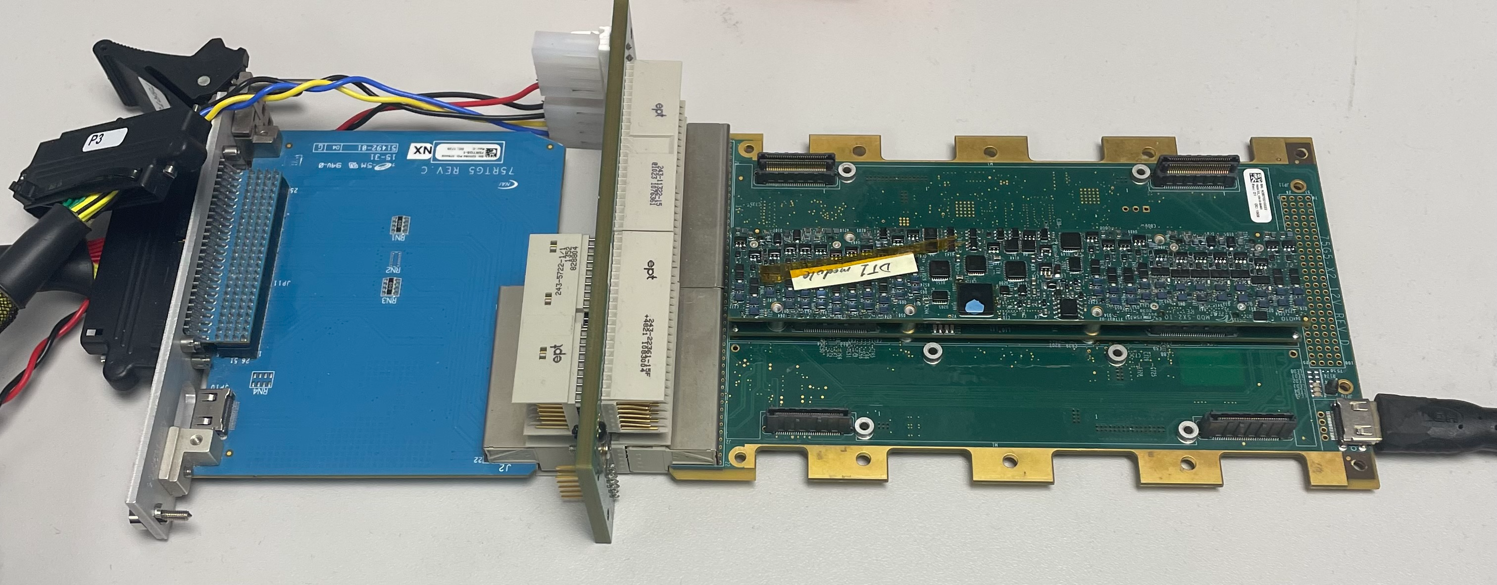
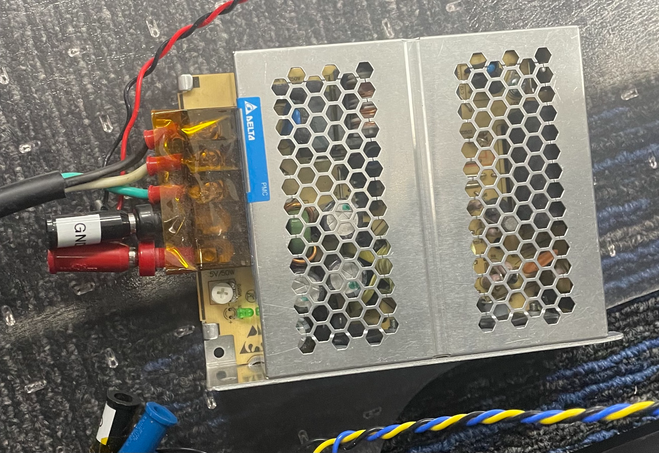
Place the module onto your board and connect the board to a power source. Then, connect the board to a PC using an ethernet cable. See an example hardware set-up below.
Software Setup
In order to configure any components of a module, you will need to download and set up the Embedded Soft Panel 2 (ESP2).
Handling the WDT
The WDT in the modules use the 'windows' method that involves Quiet Time and Open Window. We will be configuring these values to see a sequence of successfull sequences. We will also change these values slightly to see what happens in the event of signal being sent at the wrong time.
Now, after connecting a module (we will use the DT4 module) to ESP2, your main layout should look like this with a 'Watchdog' tab on the top-left table. If the tab is missing, this could mean your module does not have a built-in WDT.
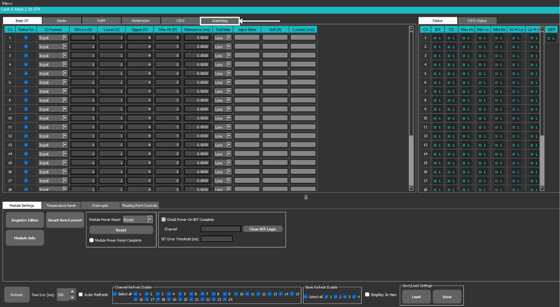
If you click the tab, you’ll be brought to the timer’s configuration settings. Here, you can configure the Quiet Time, Window, and Period (time between each strobe/signal). Then, you can click Auto Set to automatically load in the default values for these settings.
You can also see the WDT status to the right. If the WDT gets triggered, then a flag will be raised here.

Now, we can start the WDT by clicking 'Start Strobing'. Click 'Stop Strobing' after some time to analyze your results. We can see that after each period (give or take a few seconds), a strobe is fired and if that strobe does not break any rules of the windows, the result will be 'Pass'. If we were to plot when these strobes occured on a number line in comparison to where the Quiet Time and Open Windows start and end, we can see that every strobe fell within the Open Window time.
Note that the first strobe failed. This is normal as a strobe is usually fired when the WDT starts to enable the timer, even though our Quiet Time would be active at that point.
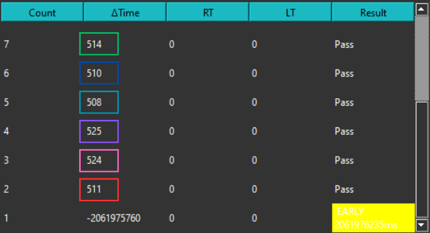
We can see that our strobes all pass. We can visualize this along a numberline. It’s important to note that after 1000mms (450ms + 100ms + 450ms), the windows get reset. This ensures that the strobes do not fall behind.

However, if we change the period to be a value that would go outside the accepted window (like 600ms), our strobes would fail and the WDT would be triggered. We can see this happen below. We can also see that an interrupt gets raised, indicating how the the WDT was, in fact, triggered.

You can also see that the output for the channels were stopped. For example, before, we could see that Ch. 4 was outputting 1.2V, but after the WDT failed, the Voltage dropped to 0V.

↓

Overall, the WDT for the modules are constantly expecting a strobe to be fired. When a strobe is fired at the wrong time, or not at all, a failure will be noted and the WDT will be triggered.
Use Case 2 - Handling the Motherboard Watchdog Timer
In this example, we are going to connect to a motherboard and configure the WDT by loading a value for the countdown, starting the WDT, and 'petting' it to reset its timer.
Hardware Setup
To hook up a motherboard, you will need:
-
A motherboard with a built-in WDT
-
A chasis to insert the board into
-
A power source
-
An ethernet cable (or another way to connect the board to your PC)
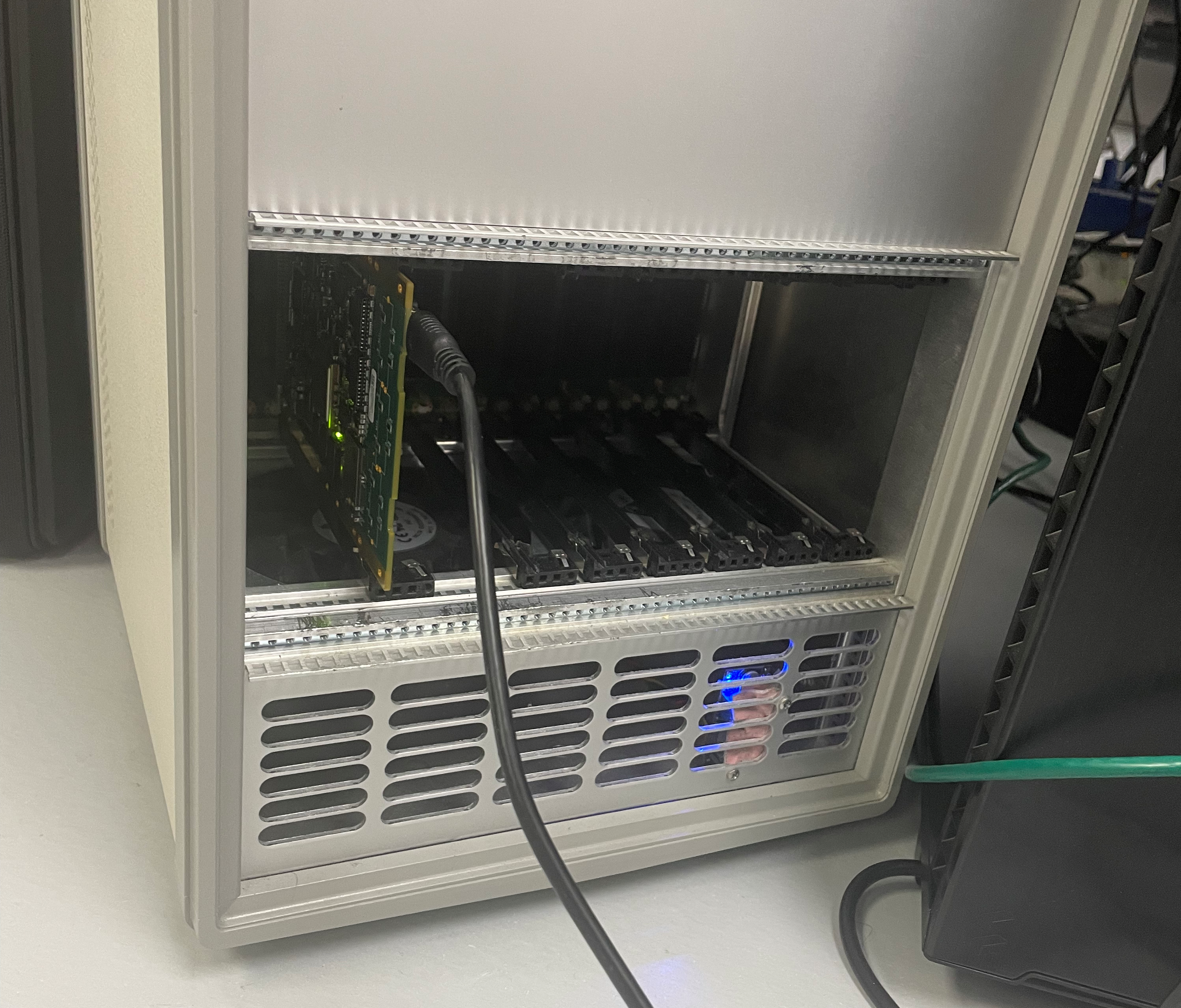
Place the motherboard into the chasis and connect it to a power source. Connect the chasis to your PC via ethernet. See an example set-up below of a motherboard and chasis.
Software Setup
To control the WDT from your PC, you will need to download Xilinx 2018, TeraTerm, WinSCP, and PetaLinux. You will also need to download NAI’s Software Support Kit 2 (SSK2) which calls NAI’s Board Support Package (BSP), allowing manipulation of the board’s registers.
The uses of all these softwares can be seen below:
-
SSK2: Provides APIs to easily access parts of the motherboard
-
Xilinx: Serves as the IDE for any C code to control the motherboard
-
PetaLinux: Provides software tools to build any C code in Xilinx
-
TeraTerm: Serves as the terminal that can connect to our device
-
WinSCP: Allows us to transfer our executable files to run them
Handling the WDT
After setting up both the hardware and software, you are now able to write code and call APIs that can manipulate the WDT.
In this example, we will use Xilinx to create a program that initializes a WDT and 'pets' it every 2 seconds until we decide to disable it.
First, aftering creating a project with a source file and a main method in Xilinx, we need to 'open' the WDT.
nai_status_t status; //Allows us to record the status of our program
int8_t boardName[20]; //A variable to store the board name

naiapp_GetBoardName(cardIndex, (int8_t *)&boardName); //Getting our board name
status = naidev_OpenDevice(cardIndex, NAI_COMM_NOT_OPEN, NAI_PERIPHERAL_BOARD_WDT, boardName); //Opening the WDT

// Prints out messages depending on our program's status
if (status == NAI_SUCCESS)
{
    naiif_printf("Watchdog timer initiated!\r\n");
}
    else
{
    naiif_printf("Could not open watchdog, status 0x%X\r\n", status);
}
After initializing, we can choose what the WDT does if its triggered.
status = naidev_Watchdog_SetExpiryBehavior(cardIndex, NAIBSP_TIMER_WDT_EXPIRY_TYPE_PROCESSOR_INTERRUPT); // WDT triggers an interrupt

if (status == NAI_SUCCESS)
{
	naiif_printf("Watchdog configured!\r\n");
}
else
{
	naiif_printf("Could not configure watchdog, status 0x%X\r\n", status);
}
We can also choose the WDT’s initial countdown value. This is the value the timer starts at and will count down from until it hits 0. It is also the value the WDT will be reset to if it is 'pet'.
status = naidev_Watchdog_LoadSeconds(cardIndex, 10); //Timer Starts at 10 Seconds

if (status == NAI_SUCCESS)
{
	naiif_printf("Watchdog timer set!\r\n");
}
else
{
	naiif_printf("Could not set watchdog timer, status 0x%X\r\n", status);
}
Finally, we can write code to start the WDT, pet it every 2 seconds, and stop it afterwards.
status = naidev_Watchdog_Start(cardIndex);
if (status == NAI_SUCCESS)
{
	naiif_printf("Watchdog timer started!\r\n\n");
}
else
{
	naiif_printf("Could not start watchdog, status 0x%X\r\n\n", status);
}

// Pet the Watchdog every 2 seconds across 5 iterations to reset the timer
for (int i = 0; i < 5; i++) {
	naibrd_usWait(2000000); //Waits for 2 seconds
	status = naidev_Watchdog_Pet(cardIndex);
	if (status == NAI_SUCCESS)
	{
		naiif_printf("Watchdog pet!\r\n");
	}
	else
	{
		naiif_printf("Could not pet watchdog, status 0x%X\r\n"status);
	}
}

//Stopping the WDT
naibrd_usWait(2000000);
status = naidev_Watchdog_Stop(cardIndex);
if (status == NAI_SUCCESS)
{
	naiif_printf("\nWatchdog timer stopped!\r\n");
}
else
{
	naiif_printf("\nCould not stop watchdog, status 0x%X\r\n", status);
}
Now that our code is complete, we can build and execute it in TeraTerm. First, build the project in Xilinx. This will generate a .elf file that can be run in TeraTerm. Transfer this file to anywhere in our file system using WinSCP. That way, TeraTerm can access our file.

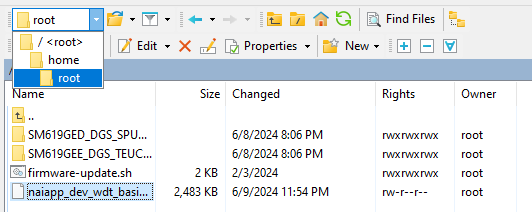
Next, we can open up TeraTerm and connect it with the correct port and Serial Proxy settings. Once connected, we can navigate across our file system. Locate where our file is and run it. See the commands below.
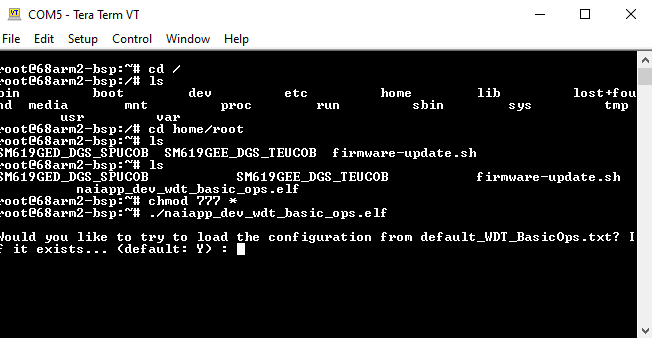
From here on, enter the correct board settings, so that we can connect our motherboard. Once that is done, the file will run our code automatically. See below what our output is:
