Interrupts
Edit this on GitLab
Introduction
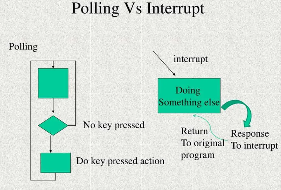
An interrupt is a signal that prompts the processor to temporarily halt its current activities and execute a specific piece of code in response to an event. Interrupts operate based on the principle of event-driven programming. Instead of continuously polling for changes, a device can notify the processor when it needs attention, improving efficiency and responsiveness. This guide will provide an overview of interrupts, how they work, and how to use them in your applications.
Use Cases
Interrupts are used to handle events that require immediate attention, such as hardware signals, timers, and user inputs.
-
Defense: In military systems, interrupts are critical for handling real-time data from sensors, managing communication signals, and responding to emergency situations. For example, radar systems use interrupts to process signals in real-time, ensuring timely detection and response to potential threats.
-
Commercial: In consumer electronics, interrupts are used for various applications such as touch screen interfaces, where immediate response to user inputs is crucial. Additionally, interrupts are employed in communication devices to manage data transmission and reception efficiently, ensuring smooth and reliable operation.
-
Industrial: In automated systems, interrupts are essential for real-time monitoring and control. For instance, interrupts can detect overvoltage conditions in power systems, triggering immediate protective measures to prevent damage. They are also used in manufacturing processes to handle critical events like equipment malfunctions or quality control alerts, ensuring minimal downtime and maintaining productivity.
Features and Advantages
-
Edge and level-triggered interrupts
-
Vector numbering for identifying interrupt sources
-
Multiple interrupt sources
-
Low-latency interrupt response
These features allow for responsive, efficient, and flexible handling of various events, making systems more reliable and performant.
Theory of Operation
Interrupts can signal the processor to execute a specific Interrupt Service Routine (ISR) when an event occurs. The processor temporarily suspends its current task, saves its state, and jumps to the ISR (which is basically a function).
Level vs Edge Interrupts
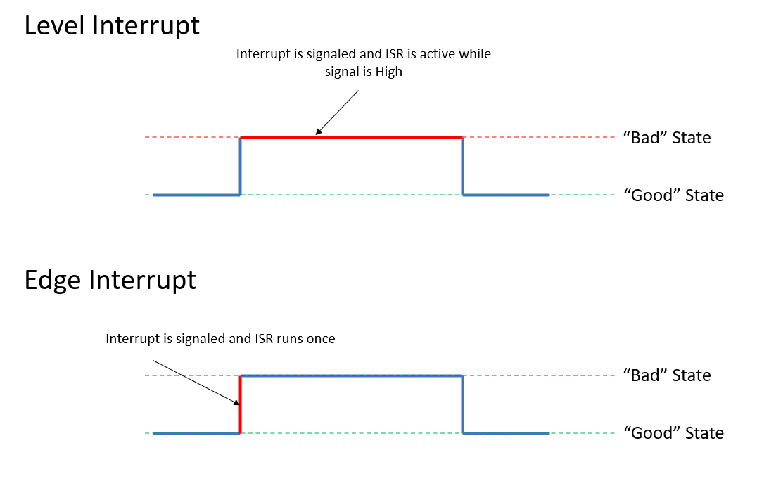
Level-Triggered Interrupts:
-
Level-triggered interrupts remain active as long as the interrupt condition is present.
-
The processor executes the ISR until the interrupt condition is cleared.
-
Level Interrupts run until you return to the "good" state.
Edge-Triggered Interrupts:
-
Edge-triggered interrupts are activated by a specific transition of the interrupt signal (e.g., rising or falling edge).
-
The processor responds to the edge transition and executes the ISR once.
-
Edge Interrups assume that after the interrupt you automatically return to the "good" state.
Vector Numbering
-
Each interrupt source is assigned a unique vector number.
-
Vector numbers are 32 bit addresses.
-
Vector numbers can be formatted in any way that the system designer chooses.
-
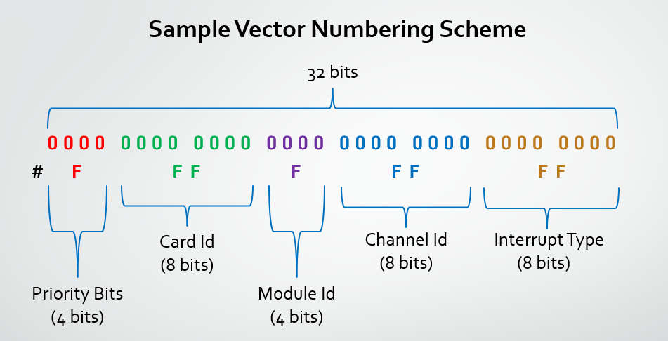
Here is one example of how vector numbers can be formatted:
-
Priority: The priority of the interrupt source.
-
Card ID: The ID of the card generating the interrupt.
-
Module ID: The ID of the module generating the interrupt.
-
Channel ID: The ID of the channel generating the interrupt.
-
Interrupt Type: The type of interrupt (e.g., TxComplete, RxComplete).
-
Extra Information: Additional information about the interrupt source.
Vector numbers are used to identify the source of the interrupt and direct it to the appropriate ISR. Additionally, vector numbers can be used to trace the source of the interrupt and debug the system.
Steering / Multiple ISR
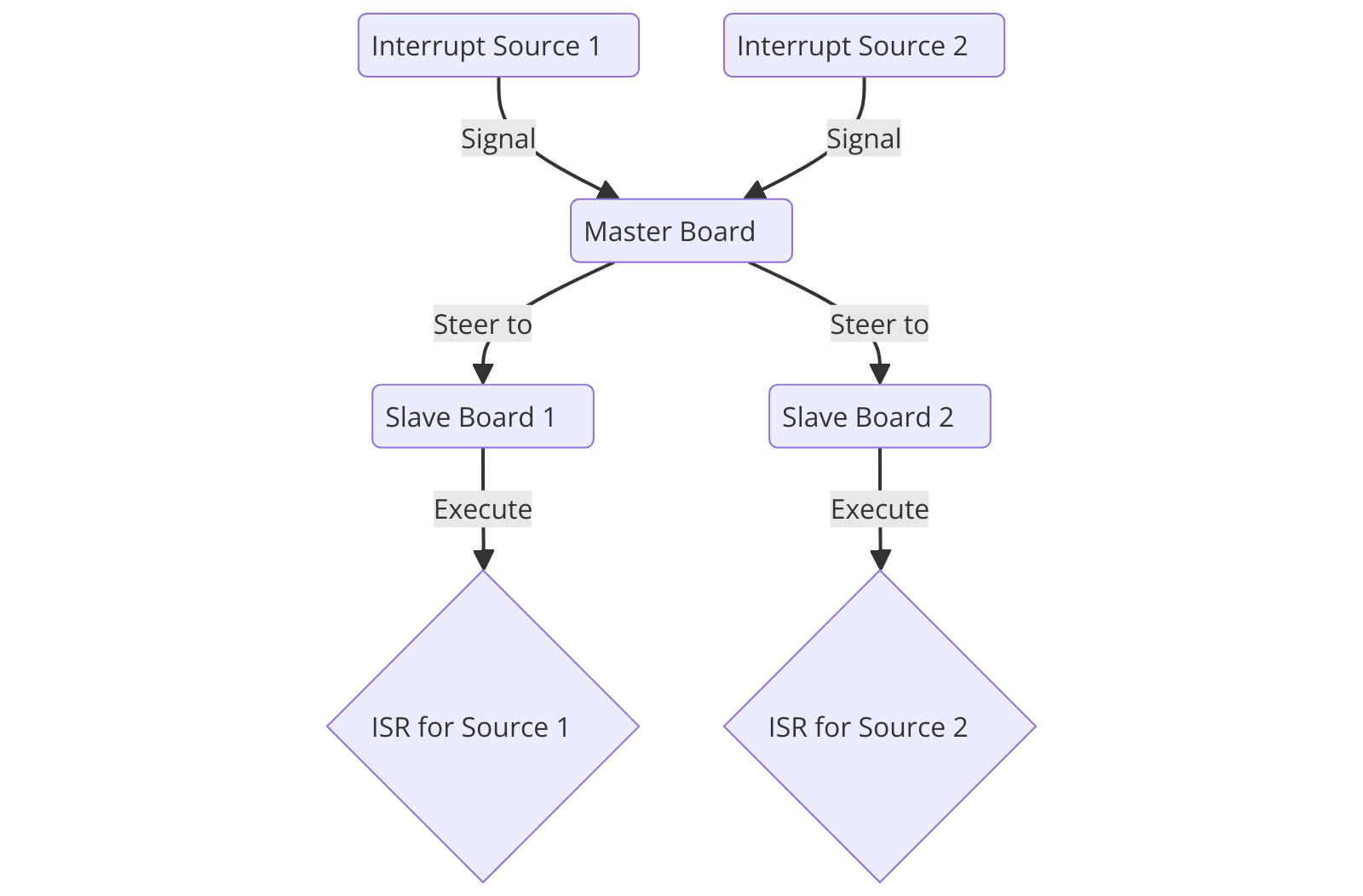
Interrupt steering is the mechanism that determines how and where an interrupt signal is directed within a system. It ensures that interrupts are processed by the most appropriate processor or interrupt handling mechanism.
For example, when we have a master board and multiple slave boards, the master board can steer interrupts to the appropriate slave board based on the source of the interrupt.
Using the Multiple ISR functionality NAI has custom ISRs can be written for each interrupt source, and the steering mechanism will direct the interrupt to the correct ISR based on the source of the interrupt.
Latency
In order to measure the latency we need to measure the time between the interrupt signal and the start of the ISR execution.
The interrupt goes through a few layers before the ISR is executed:
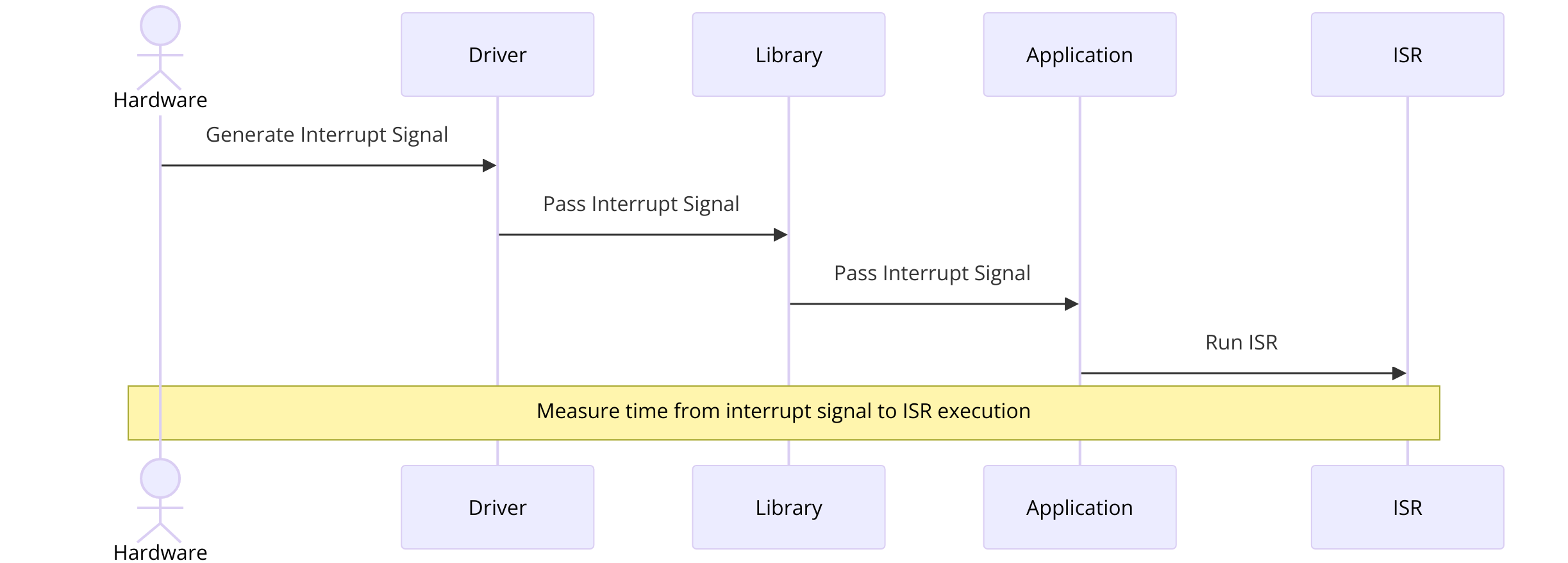
-
The interrupt signal is generated by the hardware.
-
The driver layer receives the interrupt signal.
-
The library layer gets the interrupt from the driver.
-
The interrupt is passed to the Application layer which runs the ISR.
By measuring the time between the interrupt signal and the start of the ISR execution, we can determine the latency of the system. This latency is crucial for real-time systems where immediate response is required.
To do this we can write a simple application with the following steps: 1. Write an ISR that listens for the TxComplete interrupt and logs the time when the interrupt is received. 2. Write an application to transmit a message and log the time. 3. Subtract the two times, we can calculate the latency.
With this method, I was able to measure the latency of the system to be 4.7 milliseconds. This is a very low latency and is suitable for real-time applications.
Project Guide
Overview
This project demonstrates how to set up and handle interrupts on a serial communication module using North Atlantic Industries (NAI) hardware. The interrupt will be triggered when a specific message is received.
Goals
You will learn how to configure and handle interrupts in serial communication, understand the use of NAI libraries, and integrate them into a real-world application.
-
what does the whole project look like (photo of full setup)
-
what will you be able to do after reading this guide (next steps)
-
what resources are available?
-
why did you choose this specific hardware for this application
Requirements
-
what hardware and software is needed for this example
-
what can they do if they do not have hardware
Getting Connected
-
how to get connected
-
pin mapping
-
connecting oscilloscopes, setting up breakout boards etc
Developing Code
-
mix these 3 sub categories together to match the natural progression
Software Support Kit
The NAI Software Support Kit (SSK) provides a set of libraries and tools to configure and handle interrupts on NAI hardware. The SSK simplifies the process of setting up interrupts and allows you to focus on developing your application.
Setting Up Interrupts
Setup_SER_Interupt(cardIndex, modNum, type[chanIndex], vector[chanIndex]);This function sets up an interrupt for a specific card, module, channel, and interrupt type. The interrupt will be triggered when the specified event occurs.
Clearing Interrupts
Clear_Interupt(cardIndex, modNum, type[chanIndex]);This function clears the interrupt for a specific card, module, channel, and interrupt type.

