NAI Ethernet Protocols
Edit this on GitLab
Summary
North Atlantic Industries values efficient and secure data transfer across all your rugged devices for your needs. Our Generation 5 motherboards come equipped with high-speed ethernet capabilities to give you a consistent, reliable, and efficient method of configuring your high-tech systems. Additionally, our Software Support Kit (SSK) provide a variety of functions to interact with the NAI embedded function modules.
Applications
NAI’s ethernet interface provides you with a variety of functions to control your motherboard’s ethernet capability for all your needs. Some examples of how you can use the NAI Gen-5 Ethernet capabilities are:
- Remote Monitoring and Control
-
Control and monitor your embedded systems remotely.
- Data Acquisition and Logging
-
Collect data from your sensors and other sourced in your embedded system, then transmit the data over Ethernet to whoever you need.
- Inter-Device Communication
-
Communicate between multiple embedded devices with your Gen-5 Motherboard within a network.
- Firmware Updates
-
Deploy firmware updates to your embedded devices remotely to maintain and upgrade devices without the need for physical access.
And more! The possibilities are endless with the NAI Gen-5 Motherboards and SSK ethernet functionality.
Features
-
Protocol Support
-
Supports both IPv4 and IPv6 protocols.
-
Compatible with TCP and UDP protocols.
-
-
Message Framework
-
Structured message format with Preamble, SequenceNo, Type Code, Message Length, Payload, and Postamble.
-
Big-endian implementation for all multi-byte fields.
-
-
Addressing
-
Supports Onboard and Off-board addressing.
-
Utilizes a Master/Slave configuration for Off-board addressing.
-
-
Register Commands
-
ReadRegsandWriteRegscommands for reading and writing single or multiple registers. -
Flags to define Onboard/Off-board addressing, SERDES block usage, and register size (32-bit or 16-bit).
-
-
Payload Handling
-
Payload elements are shown in green in the message table descriptions.
-
Variable payload size based on command type.
-
-
Interrupt Driven Response (IDR) and Timer Driven Response (TDR)
-
Mechanisms to execute commands based on timer events or interrupts.
-
Supports asynchronous listening for responses.
-
-
Scripting
-
Supports command scripting to execute sequences of predefined interface commands.
-
Up to 16 scripts can be defined with a maximum of 100 commands per script.
-
-
Error Handling
-
Comprehensive error response codes for various invalid operations or conditions.
-
Advantages
-
Versatility
-
Supports a wide range of protocols and addressing modes, making it adaptable to various networking environments.
-
-
Structured Communication
-
Well-defined message framework ensures reliable and organized data transmission.
-
-
Flexibility
-
Supports both synchronous (Command/Response) and asynchronous (TDR/IDR) communication modes.
-
-
Scalability
-
Dynamic module addressing allows for flexible and scalable network configurations.
-
-
Error Detection and Handling
-
Robust error detection and handling mechanisms enhance system reliability.
-
-
Efficient Command Execution
-
Scripting capability allows for efficient execution of multiple commands, reducing overhead and improving performance.
-
-
Comprehensive Functionality
-
Wide range of commands for register operations, FIFO reading, block commands, and scripting, covering diverse use cases.
-
-
Ease of Use
-
Clear definitions of commands, responses, and error codes simplify the development and debugging process.
-
Product Offerings
The NAI Ethernet Interface for NAI Single Board Computers (SBC) and Multi-Function I/O boards only applied to the Generation 5 boards. A table of supported products is provided below:
NIU1A |
75G5 |
68G5 |
64G5 |
75ARM1 |
75PPC1 |
75INT2 |
64ARM1 |
65PPC1 |
64INT2 |
Ethernet Message Framework
All messages begin with a Preamble code and end with a Postamble code. The message framework is shown below:
|
Note
|
All multibyte fields are implemented as big endian |
Preamble |
The Preamble is used to delineate the beginning of a message frame. The Preamble is always 0xD30F. |
SequenceNo |
The SequenceNo is used to associate Commands with Responses. |
Type Code |
Type Codes are used to define the type of Command or Response the message contains. |
Message Length |
The Message Length is the number of bytes in the complete message frame starting with and including the Preamble and ending with and including the Postamble. |
Payload |
The Payload contains the unique data that makes up the command or response. Payloads vary based on command type. Payload elements are shown in green in the message table descriptions. |
Postamble |
The Postamble is used to delineate the end of a message frame. The Postamble is always 0xF03D. |
Theory of Operation
Block Commands
The NAI ethernet interface supports block read writes. A block is a list of register addresses to be read or written in a singular operation.
The following block commands are supported:
-
SetBlockConfig: Defines a block configuration -
GetBlockConfiguration: Retrieves a block configuration -
ClearBlockConfig: Clears a block configuration -
ReadBlock: Reads registers defined in block configuration -
WriteBlock: Writes registers defined in block configuration
A block definition consists of the following fields:
-
BlockID: 2 bytes. -
Flags: 2 bytes. Same definition as forReadRegs/WriteRegs. -
Bit 0: Onboard/Offboard Addressing. 0 - Onboard, 1 - Offboard. -
Bit 4: 32-bit/16-bit register size. 0 - 32-bit, 1 - 16-bit. -
Register Count: 2 bytes. Number of registers defined in block. -
Register Addresses: 4 bytes. List of register addresses.
|
Note
|
Onboarding addressing refers to accessing resources located on the board that is implementing the operation interface, including the modules. Offboard addressing refers to accessing resources located on another board reachable via VME, PCI, or other bus. Off-board addressing requires a Master/Slave configuration. |
Block commands differ from the basic ReadRegs/WriteRegs commands because they allow for non-patterned multiple register reads or writes. The addresses can be in any order and not be defined by any particular pattern. All registers specified within a block are bound by the same flag settings. You cannot mix Onboard/Off-board addressing or 32-bit/16-bit register sizes.
ZBlock Commands
The NAI Ethernet Interface also supports ZBlock reads and writes. Like a block, a ZBlock is a list of register addresses to be read or written in a single operation. Unlike regular blocks, ZBlocks may contain Onboard and Offboard addresses in a single block.
The following block commands are supported:
-
SetZBlockConfig: Defines a ZBlock configuration -
GetZBlockConfig: Retrieves a ZBlock configuration -
ClearZBlockConfig: Clears a ZBlock configuration -
ReadZBlock: Reads registers defined in ZBlock configuration -
WriteZBlock: Writes registers defined in ZBlock configuration
A ZBlock definition consists of the following fields:
-
ZBlockId: 2 bytes. -
Flags: 2 bytes. Same definition as forReadRegs/WriteRegs. -
Bit 0: Onboard/Offboard Addressing. 0 - Onboard, 1 - Offboard. -
Bit 4: 32-bit/16-bit register size. 0 - 32-bit, 1 - 16-bit. -
Register Count: 2 bytes. Number of registers defined in ZBlock. -
Register Addresses: 4 bytes. List of register addresses.
ZBlock commands differ from ReadRegs/WriteRegs commands because they allow for non-patterned multiple register reads or writes. In other words, the addresses can be in any order and not be defined by a particular pattern. All registers defined in a ZBlock must be either 32-bit or 16-but in register sizes — you cannot mix 32-bit and 16-bit register commands in a single ZBlock.
Timer Driven Response (TDR) Commands
TDRs (also known as Unprompted Reply Commands) execute a list of commands based on a timer event, requiring asynchronous listening for responses triggered by timers. While similar to Interrupt Driven Responses (IDR), TDRs use a timer period instead of an interrupt vector.
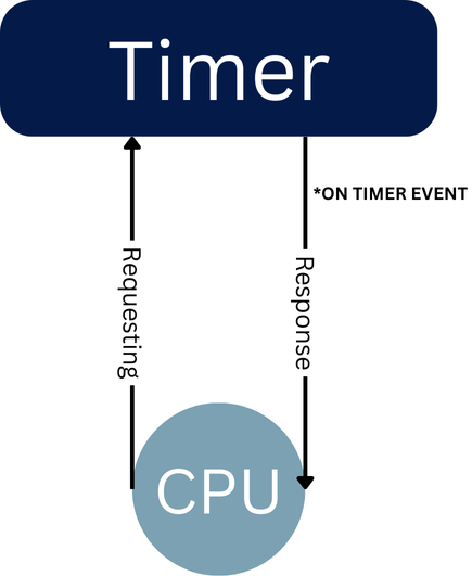
The following TDR commands are supported:
-
SetTDRConfig: Defines a TDR configuration -
GetTDRConfig: Retrieves a TDR configuration -
ClearTDRConfig: Clears a TDR configuration -
StartTDR: Starts the timer for the TDR -
StopTDR: Stops the timer for the TDR
A TDR definition consists of the following fields:
-
TDR Id: 2 bytes. Unique Id (1-16). -
Response Protocol: 2 bytes. 0 - TCP, 1 - UDP. -
Response IP Address Length: 2 bytes. 4 bytes for IPv4, 16 bytes for IPv6. -
Response Address: 4 or 16 bytes. Destination IP address. -
Response Port: 2 bytes. Destination port. -
Period: 2 bytes. Period in milliseconds, ranging from 40 - 65535. -
Command Count: 2 bytes. Number of commands to execute. -
Commands: List of commands fromReadRegs,WriteRegs,ReadBlock, andWriteBlock.
There are a maximum of 16 definable TDRs. Each TDR can contain up to 4 commands.
TDRs use SequenceNo’s to identify the TDR to which a particular response belongs. The SequenceNo is provided by the following formula:
\$SequenceNo == 0x8000 | (uhTDRIndex << 10) | (uhCommandIndex << 6)\$
This provides the mechanism to identify the TDR for which an Unprompted Replay is associated with.
The Bit assignments for SequenceNo’s is as follows:
-
Bit 15: IDR Response -
Bit 14: TDR Response -
Bit 13-10: TDR/IDR Index. TDRIndex = TDRId - 1, IDRIndex = IDRId - 1. -
Bit 9-6: Command Index = CommandID - 1. -
Bit 5-0: Reserved.
Interrupt Driven Response (IDR) Commands
IDRs (also knwon as Unrpompted Reply Commands) execute a list of commands based on an interrupt, requiring asynchronous listening for responses. While similar to Timer Driven Responses (TDR), IDRs use an interrupt vector instead of a timer period.
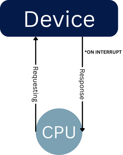
The following IDR commands are supported:
-
SetIDRConfig: Defines an IDR configuration -
GetIDRConfig: Retrieves an IDR configuration -
ClearIDRConfig: Clears an IDR configuration -
EnableIDR: Enables execution of associated commands on the specified interrupt -
DisableIDR: Disables execution of associated commands on the specified interrupt
An IDR configuration consists of the following fields:
-
IDR Id: 2 bytes. Unique Id (1-16). -
Response Protocol: 2 bytes. 0 - TCP, 1 - UDP. -
Response IP Address Length: 2 bytes. 4 bytes for IPv4, 16 bytes for IPv6. -
Response Address: 4 or 16 bytes. Destination IP address. -
Response Port: 2 bytes. Destination port. -
Vector: 4 bytes. Valid values range from 0x00000000 to 0xffffffff. -
Command Count: 2 bytes. Number of commands to execute. -
Commands: List of commands fromReadRegs,WriteRegs,ReadBlock, andWriteBlock.
Commands contained the command list follow the same message protocol as all other commands. Each command must contain the full Header, Payload, and Trailer fields. A maximum of 16 IDRs may be defined. Each IDR may have up to 4 commands.
IDRs use SequenceNo’s to identify the TDR to which a particular response belongs. The SequenceNo is provided by the following formula:
\$SequenceNo == 0xC000 | (uhIDRIndex << 10) | (uhComm$andIndex << 6)\$
This provides the mechanism to identify the TDR for which an Unprompted Replay is associated with.
The Bit assignments for SequenceNo’s is as follows:
-
Bit 15: IDR Response -
Bit 14: TDR Response -
Bit 13-10: TDR/IDR Index. TDRIndex = TDRId - 1, IDRIndex = IDRId - 1. -
Bit 9-6: Command Index = CommandID - 1. -
Bit 5-0: Reserved.
Scripting Commands
The NAI Ethernet Interface also supports scripting commands. This allows the user to assemble sequences of predefined commands that are stored in the operation memory of the Motherboard Ether Listener process. These sequences are called scripts and are available fro the duration of the existing process only — they are not stored in on the Motherboard. On reset, all scripts are cleared from memory.
Up to 16 scripts can be defined. Each script is defined by its ScriptID (a number from 1 - 16).
Users can WriteScripts, ReadScripts, ExecuteScripts, and ClearScripts using the associated commands.
Each script can hold a maximum of 100 commands provided that the summation of all command bytes do not exceed the maximum allowable bytes (1500) per Ethernet Message.
When a script is executed, all commands are executed serially in the exact sequence they are defined in the script. Responses are generated for each command and are executed exactly as if the commands were sent individually.
The following scripting commands are provided:
-
ClearScript: Clear the contents of the designated script -
WriteScript: Write the commands to the designated script -
SetSafeStateScriptID: A single ScriptID may be designated as the SafeState script. It may be executed when SafeState criteria are met such as EtherOpMode Communication Timeout. Valid values are 1 to 16. Setting a value of 0 clears theSafeStateScriptID. -
GetSafeScriptID: Retrieves the current SafeStateScriptID. A value of 0 indicates the current SafeStateScriptID is cleared.
The following commands can be scripted:
-
NOP -
ReadRegs -
WriteRegs -
ReadFIFO -
MaskReg -
MaskValueReg
I2C Raw Commands
The NAI Ethernet Interface supports I2C reads and writes.
The following I2C commands are supported:
-
ReadI2CRaw: Reads registers over I2C -
WriteI2CRaw: Writes registers over I2C
A I2C Raw Data definition consists of the following fields:
-
Response Data Length: 2 bytes. Number of data bytes that will be returned by the command. -
I2C Command Data Length: Number of data bytes in the I2C read command. -
I2C Command: The I2C addresses command. -
I2C Command Data: The data that will be sent with the I2C read command.
System Configuration Commands
These commands are intended for Factory Test only and may not be available on all platforms.
The following System Configuration commands are supported:
-
Get System Configuration: Reads the system configuration data (Card PCI/VME data such as Base Address size, etc)
System Configuration data definition consists of the following fields:
-
Card number: 4 bytes. The card index number. -
Base Address: 4 bytes. Base address of the card. -
Size: 4 bytes. The size of the card. -
Lane: 2 bytes. The PCIe lane. -
Bus: 2 bytes. The PCI bus. -
Dev: 2 bytes. The PCI Dev. -
Func: 2 bytes. The PCI Function. -
DevId: 2 bytes. The card PCI Device ID.
Error Response Codes
Error responses wil return the error number via the TypeCode with a value between 0x8000 to 0x8FFF. The packet also contains an ASCII encoded message field which is not null terminated. RThe size of this field can be determined by subtracting 10 from the Length field. For information about valid error codes, refer to Response Type Codes.
Register Commands
There are two Register Commands: ReadRegs and WriteRegs. These commands are capable of reading or writing single or multiple registers using a pattern of addressing on the motherboard or modules. Both commands use the same set of parameters as described below:
-
Flags (2 bytes):
-
Bit 0: Onboard/Off-board Addressing: 0-Onboard, 1-Off-board
-
Bit 1: Use SERDES Blocks if Supported: ▪ 0: Do not use SERDES Blocks ▪ 1: Use SERDES Blocks NOTE: Some Module firmware releases have not reported their SERDES Block Capabilities properly. This bit flag gives the ability to disable the use of SERDES Blocks for any Module that does not implement the SERDES Blocks feature as advertised by their Module Common Capabilities register at 0x0070.
-
Bit 4: 32-bit/16-bit Register Size: 0 = 32-bit, 1 = 16-bit
-
-
Register Address (4 bytes):
-
Register start address for all reads or writes
-
-
Count (2 bytes):
-
The number of Register Size reads or writes to perform
-
-
Stride (2 bytes):
-
Number of bytes to increment the register addressing for each consecutive read or write
-
The Count parameter specifies the number of registers to read or write. The Register size is defined in the Flags parameter as either 32-bit or 16-bit. If the 16-bit flag is set, then Count represents the number of 16-bit words to read or write. If the 32-bit flag is set, Count represents the number of 32-bit words to read or write.
The Stride parameter specifies how the Register Address will be incremented while performing the Count reads or writes. The Stride parameter is always specified in bytes and only values that are a multiple of the specified register size (32-bit or 16-bit) are valid. See the notes below for specifying a valid Stride value:
-
If 32-bit (4-bytes) Register Size is specified, then only Strides which are multiples of 4 are valid. For example: 0, 4, 8, 12, 16,…
-
If 16-bit (2-bytes) Register Size is specified, then only Strides which are multiples of 2 are valid. For example: 0, 2, 4, 6, 8,…
-
A Stride of 0 results in the same address being read or written “Count” times. This is useful for reading or writing FIFOs.
-
A Stride of 2 (valid for 16-bit Register Size) results in the register address being incremented by 2 bytes for each read or write performed. This results in all memory being read consecutively (no gaps or overlap).
-
Similarly, a Stride of 4 (valid for 32-bit Register Size) results in the register address being incremented by 4 bytes for each read or write performed. This results in all memory being read consecutively (no gaps or overlap).
-
For Strides greater than the Register Size (and multiples of the Register Size) then this results in non-contiguous (gaps) memory reads.
Project Guide
To demonstrate the capabilities of the NAI Ethernet Interface, an example will be used to demonstrate its capabilities in a real-world application.
Overview
In this project, we establish a communication link between an NAI motherboard and a mission computer using the Ethernet interface to monitor system health. This setup is crucial in real-world applications, such as in defense and aerospace, where maintaining optimal system performance is vital. By retrieving data like temperature and status, the mission computer can ensure that the embedded systems are operating within safe parameters, allowing for timely interventions and adjustments. This integration enhances situational awareness and contributes to the overall reliability and safety of the mission-critical operations. In particular, we want to look at the capabilities of reading directly from ethernet and reading from the registers.
Requirements
Hardware Components:
-
An NAI Gen-5 Motherboard
-
A 'mission computer'
-
A powersupply
-
An Ethernet Cable
-
A Breakout Board
Software Components:
-
NAI’s SSK 1.0 w/ BSP
-
Visual Studio 2022
-
Python
-
Visual Studio Code
Getting Connected
Hardware Setup:
To get started, first assemble your hardware. We will need a NAI Generation 5 Motherboard for integration with the ethernet interface. In this example, we will be using a 75G5.
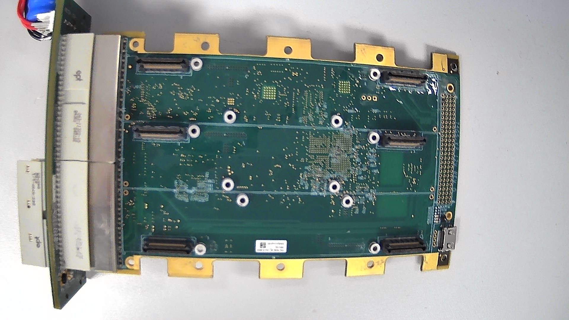
You will need an appropriate power supply for your motherboard. For the 75G5, we will need to supply 5V. Connect the ground and positive terminal of your motherboard to the corresponding terminals on your power supply like so:

Connect your ethernet cable to the back ethernet port on the motherboard like so:
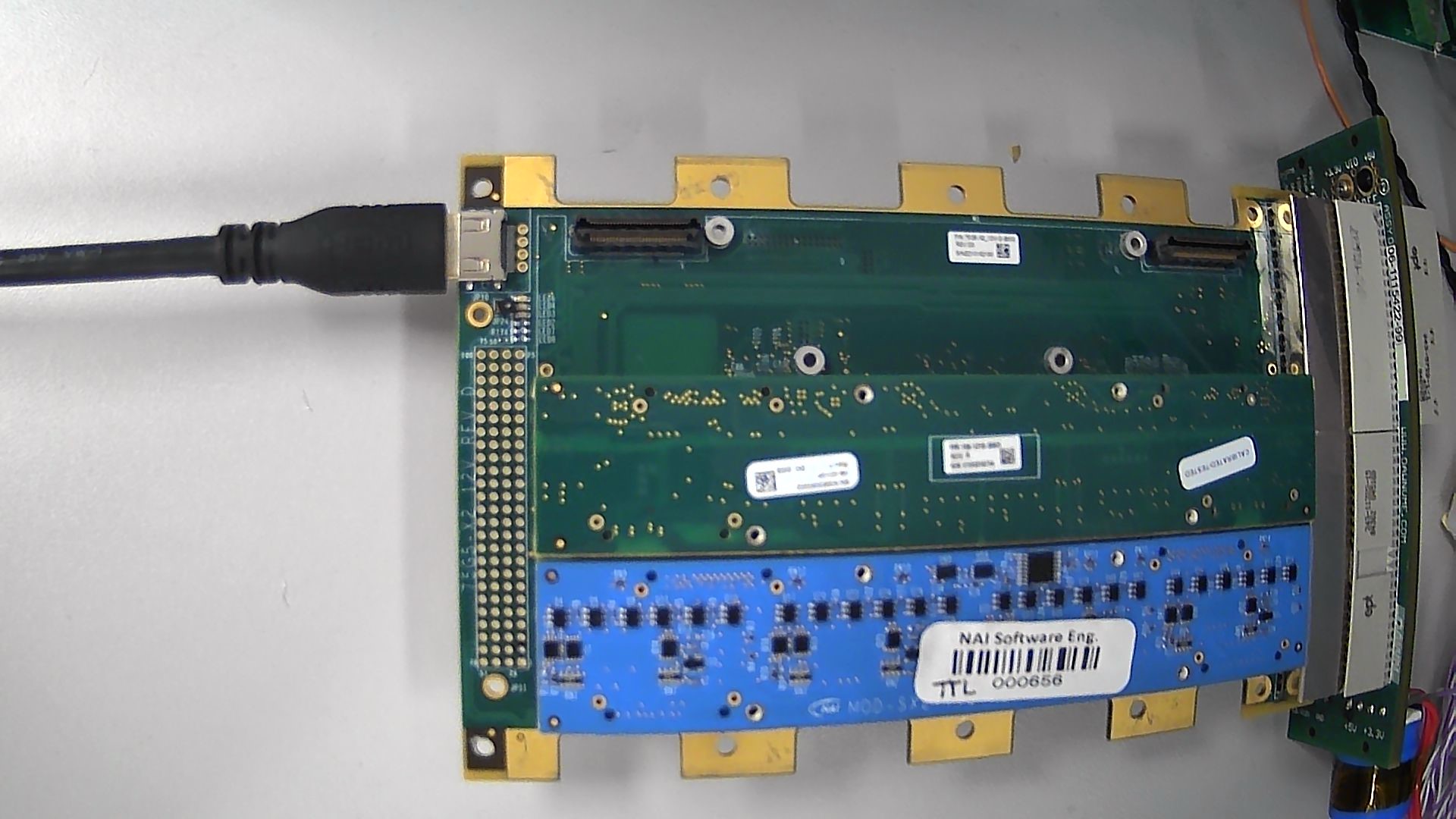
Connect the other end of your ethernet cable to the breakout board, as well as connecting the ethernet cable and serial cable for your host machine to the breakout board as well.
Now, you have configured your hardware to get started with software development.
Software Setup:
To get started, we need to download the SSK1 and configure a new project for use.
First, open the terminal on your device and navigate to a folder where you want to keep the repository.
Then, type in git clone https://gitlab.naii.com/software/ssk1.git
Next, ensure that you have downloaded and properly setup Visual Studio 2022 from the following link: https://visualstudio.microsoft.com/vs/community/
Once you have everything installed, open up the folder containing your repository in Visual Studio:
Once inside, navigate into AppSrc and right click on any of the projects inside the subfolders to copy.
You now have a project to work with. If you want to change the name of the project/source file, you must change all references of this using editor tools. For now, we will leave it as is.
Open the naibrd_Appsrc.sln now in Visual Studio to build and execute the projects.
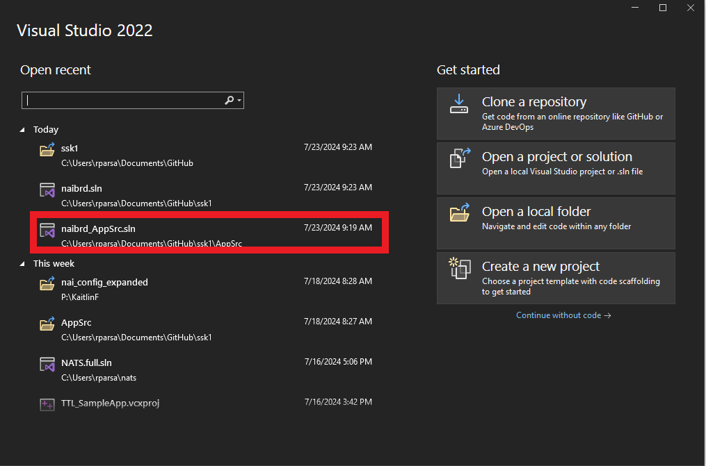
Before you begin editing your project, make sure you build the naibrd project first.
Now, we can start creating our project.
Developing Code
In this project, we want to do a few things:
-
Measure ethernet speed across various data sizes (512, 1024, 2048, 4096).
-
Measure the speed of reading directly from ethernet response buffers and reading from block registers
To get started, you need to create an external client that your motherboard is communicating with. This server needs to be run at all times so your motherboard is able to access it. Here is an example of such in python:
import socket

# Define the server address and port
SERVER_ADDRESS = '192.168.1.100'  # Listen on all network interfaces
SERVER_PORT = 12345          # Port to listen on

def start_server():
    # Create a TCP/IP socket
    server_socket = socket.socket(socket.AF_INET, socket.SOCK_STREAM)

    # Bind the socket to the server address and port
    server_socket.bind((SERVER_ADDRESS, SERVER_PORT))

    # Listen for incoming connections
    server_socket.listen(5)
    print(f"Server listening on {SERVER_ADDRESS}:{SERVER_PORT}")

    while True:
        # Wait for a connection
        client_socket, client_address = server_socket.accept()
        try:
            print(f"Connection from {client_address}")

            # Receive the data from the client
            data = client_socket.recv(1024)
            print(f"Received {data} from {client_address}")

            # Send a response back to the client
            response_message = b"Server status secure."
            client_socket.sendall(response_message)
            print(f"Sent response to {client_address}")

        finally:
            # Clean up the connection
            client_socket.close()

if __name__ == "__main__":
    start_server()
Now, let’s see some code to send a message across ethernet and print the received data:
/**************************************************************************************************************/
/**
* This function listens on the port to receive information from the mission computer and reads it directly
*/
/**************************************************************************************************************/
static bool_t naiapp_Ether_Receive(int32_t cardIndex, int bufferLen) {
    WSADATA wsaData;
    int result;

    SOCKET ConnectSocket = INVALID_SOCKET;

    struct addrinfo* addrResult = NULL;
    struct addrinfo hints;

    int recvResult;
    char* recvBuf = (char*)malloc(bufferLen);
    int recvBufLen = bufferLen;

    if (!recvBuf) {
        handleError("Memory allocation failed");
        return false;
    }

    // Initialize Winsock
    result = WSAStartup(MAKEWORD(2, 2), &wsaData);
    if (result != 0) {
        handleError("WSAStartup failed");
        free(recvBuf);
        return false;
    }

    // Setup address info
    ZeroMemory(&hints, sizeof(hints));
    hints.ai_family = AF_INET;
    hints.ai_socktype = SOCK_STREAM;
    hints.ai_protocol = IPPROTO_TCP;

    // Resolve the server address and port
    result = getaddrinfo(SERVER_IP, SERVER_PORT, &hints, &addrResult);
    if (result != 0) {
        handleError("getaddrinfo failed");
        WSACleanup();
        free(recvBuf);
        return false;
    }

    // Create a socket for connecting to server
    ConnectSocket = socket(addrResult->ai_family, addrResult->ai_socktype, addrResult->ai_protocol);
    if (ConnectSocket == INVALID_SOCKET) {
        handleError("Error at socket()");
        freeaddrinfo(addrResult);
        WSACleanup();
        free(recvBuf);
        return false;
    }

    // Connect to server.
    result = connect(ConnectSocket, addrResult->ai_addr, (int)addrResult->ai_addrlen);
    if (result == SOCKET_ERROR) {
        handleError("connect failed");
        closesocket(ConnectSocket);
        ConnectSocket = INVALID_SOCKET;
        freeaddrinfo(addrResult);
        WSACleanup();
        free(recvBuf);
        return false;
    }

    freeaddrinfo(addrResult);

    // Create the buffer with data to send
    char* sendbuf = (char*)malloc(bufferLen);
    if (!sendbuf) {
        handleError("Memory allocation failed");
        closesocket(ConnectSocket);
        WSACleanup();
        free(recvBuf);
        return false;
    }
    memset(sendbuf, 'A', bufferLen); // Fill buffer with 'A's

    // Send a request to the server
    result = send(ConnectSocket, sendbuf, bufferLen, 0);
    if (result == SOCKET_ERROR) {
        handleError("send failed");
        closesocket(ConnectSocket);
        WSACleanup();
        free(recvBuf);
        free(sendbuf);
        return false;
    }

    printf("Bytes Sent: %d\n", result);

    // Receive data from server
    recvResult = recv(ConnectSocket, recvBuf, recvBufLen, 0);
    if (recvResult > 0) {
        printf("Bytes received: %d\n", recvResult);
        recvBuf[recvResult] = '\0'; // Null-terminate the received data
        printf("Received message: %s\n", recvBuf);
    }
    else if (recvResult == 0) {
        printf("Connection closed\n");
    }
    else {
        handleError("recv failed");
    }

    // Cleanup
    closesocket(ConnectSocket);
    WSACleanup();
    free(recvBuf);
    free(sendbuf);

    return true;
}
In our main code block, we will call this function along with a time measuring function over 4 different buffer sizes to see how long it takes. Here’s some code to perform this:
   int bufferLens[] = { 512, 1024, 2048, 4096 };
   printf("\nNow testing ethernet...\n");
   for (int i = 0; i < sizeof(bufferLens) / sizeof(bufferLens[0]); ++i)
   {
      measureTransmissionTime(bufferLens[i]);
   }
The output of this code is shown below, where we can see how long it takes to send and receive messages over ethernet, saving them in an array:
Now let’s see how long it takes to do something similar using the Gen 5 Ethernet Interface’s block capabilities. Instead of reading the response directly from ethernet, we will be saving the results to block storage and then reading from the block registers.
To do so, let’s modify our transmit function slightly to include calling the block functions:
    // Receive data from server
    recvResult = recv(ConnectSocket, recvBuf, recvBufLen, 0);
    if (recvResult > 0) {
        printf("Bytes received: %d\n", recvResult);
        recvBuf[recvResult] = '\0'; // Null-terminate the received data
        printf("Received message: %s\n", recvBuf);
        WriteEthBlockRegisters(cardIndex, blockid, recvBuf, bufferLen);
        ReadEthBlockRegisters(cardIndex, blockid);
    }
Now, let’s create the new Block functions, starting with SetEthBlockConfig. This function calls This function calls InitBlockRegisters() to sets up the list of register addresses for the Set Block command
and calls naibrd_Ether_SetBlock() to send the SetBlock command to the board for the Block ID specified, which is defined to just 1 for this example. This function will be called once in the main function.
static nai_status_t SetEthBlockConfig(int32_t cardIndex, int32_t blockid)
{
printf("Setting ethernet block configuration...\n");
bool_t bQuit = FALSE;
nai_status_t status;
uint32_t address[MAX_ETHER_BLOCK_REG_CNT];
nai_intf_t inf;
uint32_t regcount = 0;
if (!bQuit)
{
InitBlockRegisters(&inf, ®count, &address[0]);
status = check_status(naibrd_Ether_SetBlock(cardIndex, (uint16_t)blockid, inf, (uint32_t)DEF_REGISTER_SIZE, regcount, address));
if (status == NAI_SUCCESS)
{
printf("Block ID = %d configured.\n", blockid);
}
}
return (bQuit) ? NAI_ERROR_UNKNOWN : NAI_SUCCESS;
}Next, let’s create InitBlockRegisters, which configures the list of register addresses for the Set Block command.
static void InitBlockRegisters(nai_intf_t* inf, uint32_t* count, uint32_t address[])
{
    printf("Initializing block registers...\n");
    int32_t index = 0;
    *inf = NAI_INTF_ONBOARD;
    *count = DEF_REGISTER_COUNT;
    /* Note, Change Default Register Size to match the register size for register specified below */
    if (bGen4BlockCommands)
    {
        /* Note: the address specified below for Motherboard and Module Common area are
                 not currently not used by the system.
        */
        /* Motherboard Common area */
        address[index++] = 0x017C;       /*  1 */
        address[index++] = 0x0180;       /*  2 */
        address[index++] = 0x0190;       /*  3 */
        address[index++] = 0x0480;       /*  4 */
        address[index++] = 0x0494;       /*  5 */
        address[index++] = 0x04A0;       /*  6 */
        address[index++] = 0x04B8;       /*  7 */
        address[index++] = 0x04C4;       /*  8 */
        address[index++] = 0x04D0;       /*  9 */
        /* Module Common area - Writing to first available module on board */
        address[index++] = 0x40D0;       /* 10 */
        address[index++] = 0x40E0;       /* 11 */
        address[index++] = 0x40F0;       /* 12 */
        address[index++] = 0x4100;       /* 13 */
        address[index++] = 0x4104;       /* 14 */
        address[index++] = 0x4114;       /* 15 */
        address[index++] = 0x4128;       /* 16 */
        address[index++] = 0x4130;       /* 17 */
        address[index++] = 0x4134;       /* 18 */
    }
    else
    {
        printf("Ethernet Block Command Support Prior to Generation 4 Ethernet commands currently not supported\n");
    }
}
Now let’s create the WriteEthBlockRegisters function, which sets up the data received via etherent to write to the list of registers via InitBlockRegistersData and sends the WriteBlock command to the board to write the data to the list of register addresses specified for the Block ID.
static nai_status_t WriteEthBlockRegisters(int32_t cardIndex, int32_t blockid, const char* recvBuf, int bufferLen)
{
    printf("Writing to ethernet block registers...\n");
    bool_t bQuit = FALSE;
    nai_status_t status;
    uint32_t data[MAX_ETHER_BLOCK_REG_CNT];

    if (!bQuit)
    {
        InitBlockRegistersData(DEF_REGISTER_COUNT, &data[0], recvBuf, bufferLen);
        status = check_status(naibrd_Ether_WriteBlock(cardIndex, (uint16_t)blockid, (uint32_t)DEF_REGISTER_SIZE, DEF_REGISTER_COUNT, data));
        if (status == NAI_SUCCESS)
        {
            printf("Block ID = %d Data written.\n", blockid);
        }
    }
    return (bQuit) ? NAI_ERROR_UNKNOWN : NAI_SUCCESS;
}
InitBlockRegistersData sets up the data to write to the list of registers for the block command by splitting up the data received by ethernet evenly to write to the block registers in order to be put back together when read later.
static void InitBlockRegistersData(uint32_t count, uint32_t data[], const char* recvBuf, int bufferLen)
{
    uint32_t chunkSize = (bufferLen + count - 1) / count; // Calculate chunk size ensuring even distribution
    uint32_t index = 0;

    for (index = 0; index < count; index++)
    {
        uint32_t value = 0;
        uint32_t copySize = chunkSize;

        // Ensure copySize does not exceed the remaining buffer length
        if ((index + 1) * chunkSize > bufferLen)
        {
            copySize = bufferLen - (index * chunkSize);
        }

        // Ensure copySize does not exceed the size of a register (4 bytes)
        if (copySize > 4)
        {
            copySize = 4;
        }

        // Copy the appropriate chunk of data from the receive buffer into the current register
        if (index * chunkSize < bufferLen)
        {
            memcpy(&value, recvBuf + index * chunkSize, copySize);
        }

        data[index] = value;
    }
}
Finally, let’s create the ReadEthBlockRegisters function, which sends the ReadBlock command to the board to retrieve the data for the list of register addresses specified for the Block ID.
static nai_status_t ReadEthBlockRegisters(int32_t cardIndex, int32_t blockid)
{
    printf("Reading from ethernet block registers...\n");
    bool_t bQuit = FALSE;
    nai_status_t status;
    uint32_t arraysize = MAX_ETHER_BLOCK_REG_CNT;
    uint32_t data[MAX_ETHER_BLOCK_REG_CNT];
    uint32_t datacount = 0;
    int32_t i;

    char message[1024] = { 0 }; // Buffer to reconstruct the message
    char* ptr = message;

    if (!bQuit)
    {
        status = check_status(naibrd_Ether_ReadBlock(cardIndex, (uint16_t)blockid, (uint32_t)DEF_REGISTER_SIZE, arraysize, data, &datacount));

        if (status == NAI_SUCCESS)
        {
            if (datacount > 0)
            {
                printf("Block ID = %d - %d\n", blockid, datacount);
            }
            else
                printf("No Registers read for Block ID = %d\n", blockid);
        }
    }
    return (bQuit) ? NAI_ERROR_UNKNOWN : NAI_SUCCESS;
}
If we run the code now, we receive the following output:
In both instances, we received the same message from the server. Although it does not necessarily take less time to read information from block registers compared to reading directly from Ethernet, there are still significant advantages to using block registers. Using block registers can simplify the management of data, provide more structured access patterns, and enhance the reliability of data retrieval by reducing the potential for errors associated with direct memory access.
With this example, we have demonstrated the benefits of using block registers for reading and writing Ethernet messages. While the speed may not always be improved, the structured approach and potential for better data management make block registers a valuable tool in certain applications. This highlights the efficiency and reliability of direct register access over traditional memory allocation in the main process.
