Backplane Reset
Edit this on GitLab
Project Guide
Tutorial Summary
In this tutorial we will go over how to set-up a Back-Plane reset with a master and slave motherboards using the 68ARM2. The goal of the tutorial is to gain a general understanding of how to set up master-slave resets on a technical hardware and software level using a 68ARM2. In this tutorial we will also discuss some of the benefits of doing these master-slave resets. After this tutorial you will be able to build upon your setup, adding more custom features using interrupts, watchdog timers, etc. for your personal applications.
The 68ARM2 motherboard is well suited for this task because it has the ability to communicate with the Slave-Boards through the backplane. One of the benefits of backplane resets is that it allows our 68ARM2 to reset a wide variety of compatible boards simultaneously. This prevents the need for each board to have individual processor reset handlers.
In addition to the resources provided in this document, there are other documents on the 68ARM2 page to get the specific settings to configure your new project up-to-date information
Requirements
Required hardware for this tutorial:
-
Two: Breakout Boards (Serial, Micro HDMI, and Ethernet required)
-
Two: Serial to USB Adapter Cable
-
Two: Micro HDMI Cable
-
One: Ethernet Cable
Use Cases

Example Projects:
Below are some examples of client projects that may require backplane resets:
-
Industrial Control System with Backplane
-
Network Switch with Backplane
-
Vehicle Electronic Control Unit with Backplane
Application to Projects:
Below are some reasons why a backplane reset benefits the above project:
Configuration Changes:
After making changes to the configuration or settings of devices connected to the backplane, a reset ensures that all components correctly initialize with the new settings.
System Maintenance:
Periodic backplane resets are often part of routine maintenance to prevent accumulation of errors, ensure reliability over time, and improve performance by clearing cached data.
Diagnostic Procedures:
During troubleshooting, resetting the backplane can help isolate and diagnose issues related to communication, synchronization, or hardware failures.
Power Cycle Recovery:
In scenarios where a power cycle affects the stability or functionality of devices connected to the backplane, resetting it can restore proper operation.
Theory of Operations
What are Motherboard Resets
A motherboard is when the computer undergoes a controlled shutdown and then reboots back on. This process involves powering off all components, including the CPU, memory modules, and peripherals connected to the motherboard. The motherboard proceeds to be powered back on, initializing the CPU and executes the system’s firmware or operating system. This reset process is essential for troubleshooting hardware issues, applying system updates that require a restart, or restoring the system to a known good state after encountering software errors or crashes. It ensures that the computer system starts afresh with all hardware components properly initialized and ready for operation.
A motherboard reset is NOT resetting the board back to a factory default state. Instead it restarts the device allowing for it to reboot and restart its previous functions.
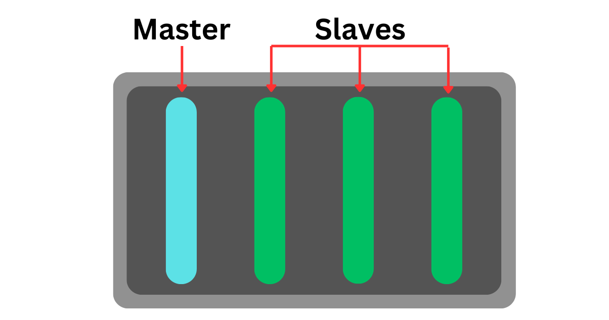
In electronics and embedded systems, the concept of master and slave boards refers to a hierarchical arrangement where one central device (the master) controls one or more peripheral devices (the slaves). The Master-Board typically initiates communication, coordinates activities, and manages data flow across the connected Slave-Boards. In contrast, Slave-Boards respond to commands from the Master-Board, performing designated functions or providing requested data. This architecture is commonly used in scenarios requiring distributed processing, such as in industrial automation, robotics, and interconnected sensor networks, where the master-slave relationship ensures efficient management of resources and cohesive system operation.
In this tutorial the Master-Board will cause a backplane reset on the chassis resetting each Slave-Board on the backplane.
Motherboard Reset Examples
The Master-Board can store the expected state of each Slave-Board. It will periodically check if the desired state is the actual state of the Slave-Board, this is called polling. In this example we will use state diagrams to represent the state of each Slave-Board.
In this example, the Master-Board polls the Slave-Board to check if it is at the right state. If the Slave-Board state doesn’t match the Master-Board’s record it can send a command to the Slave-Board to reset. This will directly turn off the desired Slave-Board allowing it to reboot. In the first example below it will bring it back to its initial start up state which is called a HARD RESET. In the second example the Slave-Board is reset, but is brought to its last good state, this is called a SOFT RESET.
Hard Reset
In this example there is a Slave-Board that did not get to the appropriate expected state when polled. This may result from an infinite loop, program crash, communication failure with the bus, or unexpected actions by the Slave-Board. If this issue happens the Master-Board can tell the Slave-Board to reset. This can be done by either sending a function call to the Slave-Board or physically power a pin to cut power to the entire backplane, resetting all Slave-Boards causing an abrupt shut down.
With the example above, the Slave-Board was hard reset so it started a completely fresh boot to begin again at state 1. This means that when the Slave-Board resets it behaves as if it is starting the program again from scratch.
Set Up
Hardware
The following set up requires all of the hardware from the Required Hardware Section
First you are going to want to set up your chassis with the 68ARM2 in the master slot and a compatible NAI board in the other slot. In the following image the Master slot is the left most board and the Slave slot is the right most board.
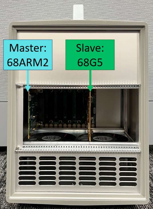
Once the boards are properly secured you’re going to want to add a Mini-HDMI cable into the ports shown below.
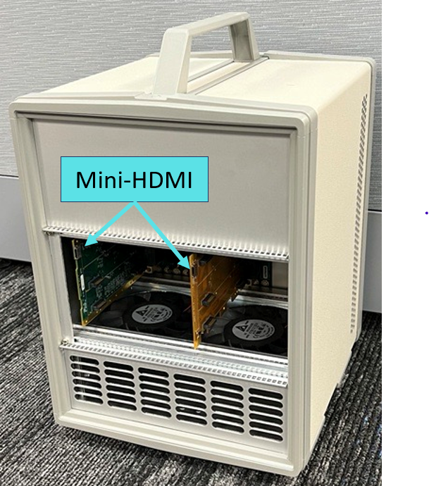
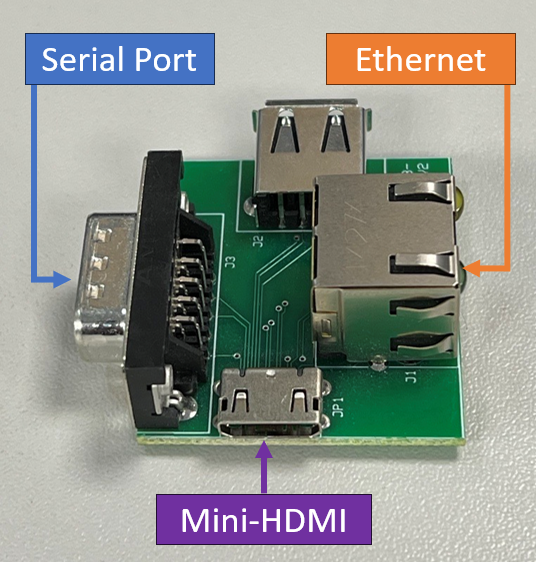
Connect each board to the following device. Then connect the serial to USB adapter and ethernet to your computer that can run Xilinx.
Software
Once your hardware is set up, you can begin setting up Xilinx write the code for your board. In this tutorial we use a 68ARM2 and therefore will be using Xilinx 2018.2.
Find the 2018.2 version of Xilinx on their download website
Once downloaded, set your workspace as your SSK 2.0 "<your path to the workspace>\PetaLinux\2023_Q4-68G6-Petalinux2018_2\petalinux-2018-2\petalinux-appsrc" directory.
Import all existing projects from petalinux-appsrc into your workspace.
Create a new project (File→New→Application Project) then select (Xilinx→ Application Project), naming it to your desired project name
Once the project is created, please see the following following Xilinx Set Up Tutorial for more specific and up to date material
Software Demo
What is Abstraction?
There are severals ways of accomplishing the same task with NAI’s SSK. NAI supplies multiple layers of abstraction to enable a smoother process in designing application code. Each layer has different levels of control given to the developer. Somewhere this can be best understood is comparing usage of dynamite versus a rock chisel. Both can accomplish the task of removing rock, but one is a one size fits all tool while the other allows for more control and precision of the environment. If the intent is to dig a tunnel through a mountain, the chisel eventually would work, but the dynamite would be faster and easier to accomplish. However if the goal is to create a marble statue a rock chisel would allow for greater control during its creation. Each tool has it purposes and NAI supplies it’s customers with both to meet any of their goals.
NAI Software Abstraction
To represent how NAI utilitzes abstraction please reference the below image. In the image abstraction is represented as different layers of the libraries and board support package (BSP). Each layer calls upon lower layers from the NAI SSK to complete the goal of the application layer. Since NAI has already written these different layers of code, the designer writing the application layer code doesn’t need to need to rewrite any of the SSK requiring knowledge of what individual registers do and how to modify them. The designer can call their desired layer of complexity to get the job done easier.
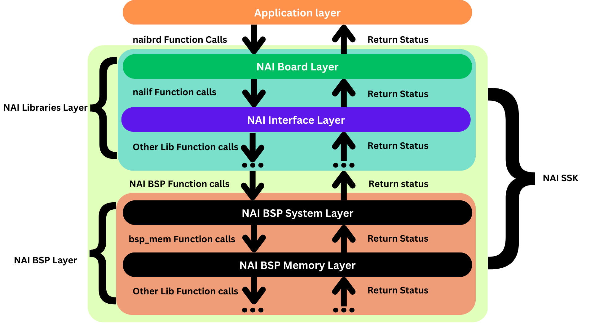
If as a application designer you want to get down into those lower layers of the board architecture, NAI encourages this by offering access to each layer. In addition to flexibility, this abstraction enables customization into which NAI libraries and NAI BSP libraries are compiled or linked into the your build. With the below example the application designer can choose what functionality they will utilize unnecessary libraries, simplifying the build process.

One benefit of utilizing the higher layers of the BSP and Libraries are their functions can be agnostic to both board type (68ARM2, 65G5, 75G5, etc.) and platform (PetaLinux, Linux, Windows, etc.). This means that the same applications can be used for very different set ups. In the following function, the programmer isn’t required to include any board or platform specific information to for the function to operate. The underlying lower level BSP layers work out the relevant information on its own to complete the task.
void reset_backplane(){
    nai_status_t status = NAI_ERROR_UNKNOWN;

    int32_t intfIndex = 1;
    status = naibsp_sys_utils_VPXReset(intfIndex);
}
In the below example, we specify a register for our 68ARM2 board can interpret as the notice to send a reset message to the backplane. When using a lower layer of the BSP like naibsp_memory, more information must be provided, such as the memory address of the register to be changed and what value it will be set to. This information is highly dependent on the board type and platform, therefore the naibsp_memory layer is NOT agnostic. Since it has to be configured to each specific board it must be used for, it is more difficult when applying this code to other platforms and board types.
void reset_backplane(){
    nai_status_t status = NAI_ERROR_UNKNOWN;

    const naibsp_memory_location_t argLocation = NAIBSP_MEMORY_MB_MODULE_CONFIG;
    naibsp_memory_region_t** NAIBSP_RESTRICT p_outRegion = NAIBSP_NULL_PTR;
    status = naibsp_memory_Init_ByLocation(argLocation, p_outRegion);

    const naibsp_memory_location_t argLocation = NAIBSP_MEMORY_MB_MODULE_CONFIG;
    const naibsp_size_t argOffset = 0x98;
    const uint32_t* const NAIBSP_RESTRICT p_inValues = NAI_MB_BUS_VPX_RESET_VAL;
    const naibsp_size_t argCount = 1;
    const naibsp_size_t argStride = 4;
    status = naibsp_memory_WriteU32_Location(argLocation, argOffset, &p_inValues, argCount, argStride);
}
Both examples will complete the same task of resetting the Slave-Board. They both modify a specific register on the Master-Board it will understand to reset the backplane, however the difference is what layer of abstraction the code itself resides on. The first example utilizes naibsp_sys, which is a higher layer than naibsp_memory. The first example can be more easily applied to other systems and devices rather than having to design a new application for a different set up.
Another benefit is neither of the examples above require the usage of a higher level NAI library. For example naibrd_ether is never utilized and therefore doesn’t need to be linked to the build for this application. This will reduce binary size and improve compile time has for the built project.
Ultimately the choice of what levels of abstraction used are up to the application designer. NAI offers these options to allow for the most flexibility to each of our customers in order to to Accelerate You Time-To-Mission.
