DIF Sample Applications
Edit this on GitLab
Introduction
Background
The DIF Modules are Differential Transceivers that transmit and receive signals to aid in communication.
Normal Differential Transceiver Functions
-
uses two complementary signals
-
offers noise immunity
-
maintains signal integrity
-
has faster speeds
NAI Product Line
NAI offers two different versions of a differential transceiver: DF1 and DF2
DF1 |
DF2 |
All Normal Transceiver Features |
All Normal Transceiver Features |
16 Programmable Channels |
16 Programmable Channels |
Programmable Time Delay |
Programmable Time Delay |
Programmable Status/Interrupts |
Programmable Status/Interrupts |
Programmable Slew Rates |
Programmable Slew Rates |
Real Time Channel Health Updates |
Real Time Channel Health Updates |
X |
Programmable PWM Modes |
X |
Pattern Generator Modes |
Available Configurations
Setting |
DF1 |
DF2 |
IO Format |
Input/Output |
Input/Output |
Debounce |
0s to 34.36s |
0s to 34.36s |
Output State |
Low/High |
Low/High |
Input Termination |
Non-Terminating/Terminating |
Non-Terminating/Terminating |
Slew Rate |
Slow/Fast |
Slow/Fast |
Read IO |
Not Configurable |
Not Configurable |
PWM |
X |
Mode Select (13 modes), Period, Pulse Width, Burst Count, Polarity |
Theory of Operation

I/O Format allows you to specify if a channel is going to be taking in signals (Input) or putting out signals (Output).
Output State allows you to specify whether your output will be High (1) or Low (0).
Read I/O allows you to read what was received in any input channels and read what was transmitted in any output channels.
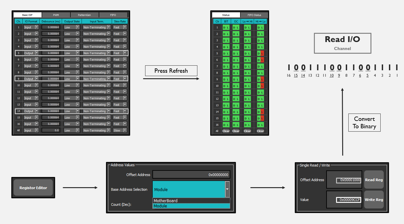
It’s important to note that all these settings are channel bit-mapped, meaning from right-to-left, each bit at the settings' registers represents the status of a channel.
For example, at register 0x1000, bit #2 represents the Read I/O of channel 2.
At register 0x1038, bit #5 represents the I/O Format of channel 5.
Mode Select: DF2
The settings for Input Mode Select are:
-
High Time Pulse Measurement
-
Low Time Pulse Measurement
-
Timestamps of Rising Transitions
-
Timestamps of Falling Transitions
-
Timestamps of All Transitions
-
Rising Edge Transition Counter
-
Falling Edge Transition Counter
-
Rising & Falling Edge Transition Counter
-
Period Measurement
-
Frequency Measurement
The settings for Output Mode Select are:
32. PWM Continuous Output
33. PWM Burst
34. Pattern Generator Output
**Modes 32 and 33 rely on the values set for Period, Pulse Width, Polarity, and Number of Cycles
Configure Settings
To configure the settings use the NAI Embedded Soft Panel (ESP) 2.0. It can be downloaded here.
The ESP is a GUI allowing users to manipulate settings for any module and see what the module does in real time.

In order to connect to the board please refer to the NAI Board Access Guide.
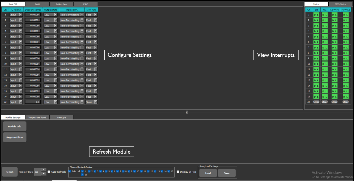
To use the ESP first configure your settings. After changing them make sure to press refresh and confirm that you are using the desired settings.
The register editor allows users to read and write to memory addresses on the module. Please note that the register values may be bitmapped for each channel.
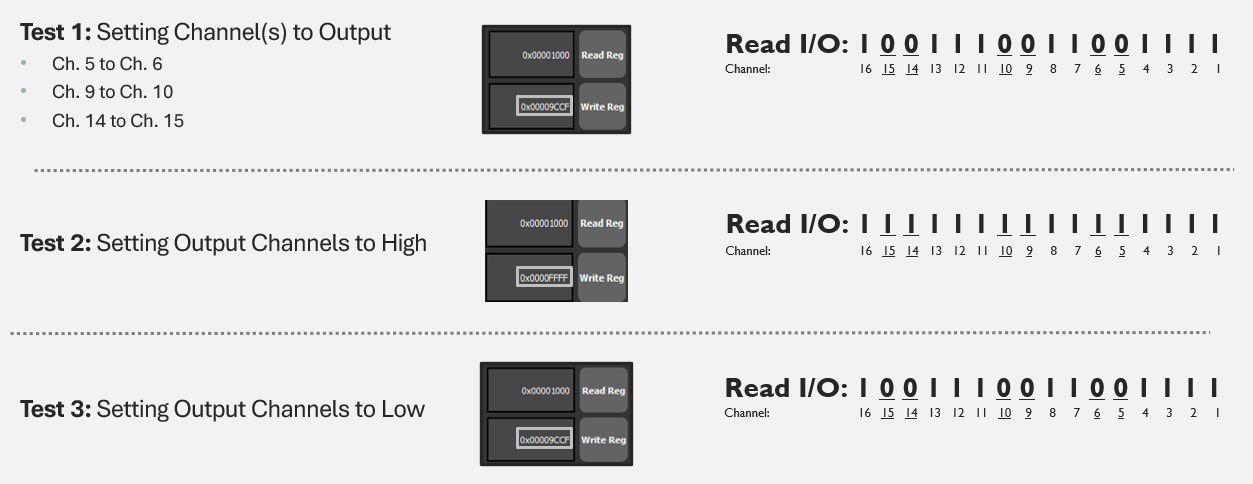
Example 1: I/O Testing
To learn how to create an application using the NAI Software Support Kit click HERE.
Once you have created your project you must first configure the channels.
Hardware
In order to have an all in one testing solution for this sample application we will create a wiring harness to connect the output pins to the input pins.
For this example we will set three of the channels to INPUT and three to OUTPUT.
status = naibrd_DIF_SetIOFormat(cardIndex, module, 5, NAI_DIF_GEN5_IOFORMAT_OUTPUT);
printf("Setting Ch. 5 as Output for Ch. 6: ");
if (status == NAI_SUCCESS) printf("SUCCESS\n");
else printf("FAILED\n");

status = naibrd_DIF_SetIOFormat(cardIndex, module, 6, NAI_DIF_IOFORMAT_INPUT);
printf("Setting Ch. 6 as Input for Ch. 5: ");
if (status == NAI_SUCCESS) printf("SUCCESS\n");
else printf("FAILED\n");

status = naibrd_DIF_SetIOFormat(cardIndex, module, 9, NAI_DIF_GEN5_IOFORMAT_OUTPUT);
printf("Setting Ch. 9 as Output for Ch. 10: ");
if (status == NAI_SUCCESS) printf("SUCCESS\n");
else printf("FAILED\n");

status = naibrd_DIF_SetIOFormat(cardIndex, module, 10, NAI_DIF_IOFORMAT_INPUT);
printf("Setting Ch. 10 as Input for Ch. 9: ");
if (status == NAI_SUCCESS) printf("SUCCESS\n");
else printf("FAILED\n");

status = naibrd_DIF_SetIOFormat(cardIndex, module, 14, NAI_DIF_GEN5_IOFORMAT_OUTPUT);
printf("Setting Ch. 14 as Output for Ch. 15: ");
if (status == NAI_SUCCESS) printf("SUCCESS\n");
else printf("FAILED\n");

status = naibrd_DIF_SetIOFormat(cardIndex, module, 15, NAI_DIF_IOFORMAT_INPUT);
printf("Setting Ch. 15 as Input for Ch. 14: ");
if (status == NAI_SUCCESS) printf("SUCCESS\n");
else printf("FAILED\n");
To ensure that the module has time to configure the channels before we use them we will use the wait function.
printf("Waiting 5 Seconds...\n");
naibrd_Wait(5000000); //Waiting for 5 seconds
printf("Finished Waiting - Changing Outputs to High...\n");
Finally, we will output signals and see if we observe the desired behavior via the ESP.
//Setting Outputs States to HIGH
status = naibrd_DIF_SetOutputState(cardIndex, module, 5, NAI_DIF_STATE_HI);
printf("Setting Ch. 5 Output to High: ");
if (status == NAI_SUCCESS) printf("SUCCESS\n");
else printf("FAILED\n");

status = naibrd_DIF_SetOutputState(cardIndex, module, 9, NAI_DIF_STATE_HI);
printf("Setting Ch. 9 Output to High: ");
if (status == NAI_SUCCESS) printf("SUCCESS\n");
else printf("FAILED\n");

status = naibrd_DIF_SetOutputState(cardIndex, module, 14, NAI_DIF_STATE_HI);
printf("Setting Ch. 14 Output to High: ");
if (status == NAI_SUCCESS) printf("SUCCESS\n");
else printf("FAILED\n");
We can also test our output with a low signal.
//Setting Output States to LOW
status = naibrd_DIF_SetOutputState(cardIndex, module, 5, NAI_DIF_STATE_LO);
printf("Setting Ch. 5 Output to Low: ");
if (status == NAI_SUCCESS) printf("SUCCESS\n");
else printf("FAILED\n");

status = naibrd_DIF_SetOutputState(cardIndex, module, 9, NAI_DIF_STATE_LO);
printf("Setting Ch. 9 Output to Low: ");
if (status == NAI_SUCCESS) printf("SUCCESS\n");
else printf("FAILED\n");

status = naibrd_DIF_SetOutputState(cardIndex, module, 14, NAI_DIF_STATE_LO);
printf("Setting Ch. 14 Output to Low: ");
if (status == NAI_SUCCESS) printf("SUCCESS\n");
else printf("FAILED\n");
|
Important
|
If you want to alternate between low and high outputs be sure to use the wait function between them. Here is an example. |
printf("Waiting 5 Seconds...\n");
naibrd_Wait(5000000); //Waiting for 5 seconds
printf("Finished Waiting - Changing Outputs to Low...\n");
The application is now complete.
Example 2: PWM Output
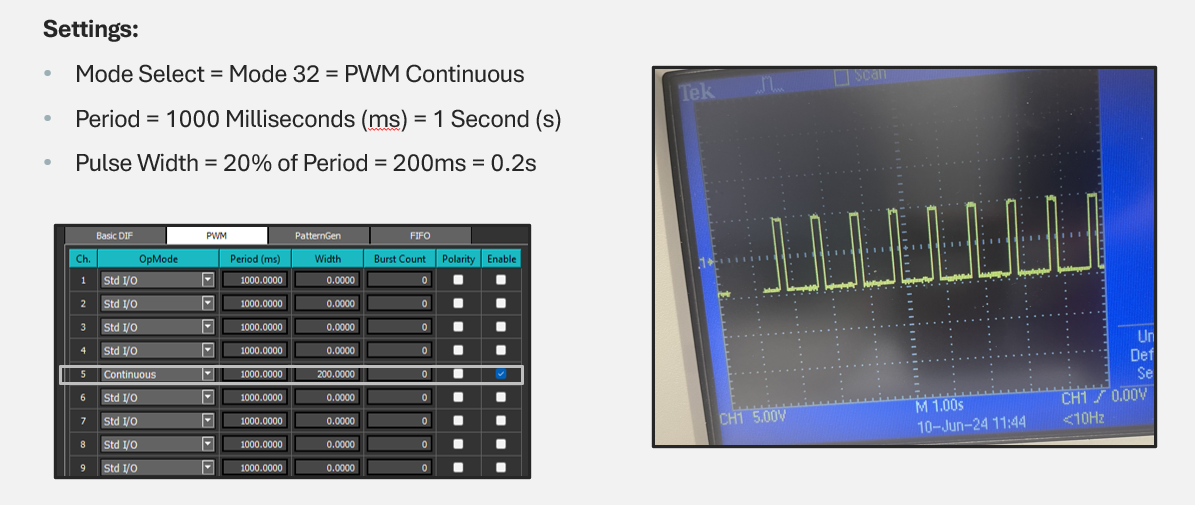
Hardware
In this example we recommend using an oscilloscope to measure your output.
First we will configure our PWM settings to the period and pulse width (duty cycle) that we desire.
status = naibrd_DIF_SetPWM_Period(cardIndex, module, 9, 1000); //Period = 1 second
printf("Period Change Status: ");
if (status == NAI_SUCCESS) printf("SUCCESS\n");
else printf("FAILED\n");

status = naibrd_DIF_SetPWM_Pulsewidth(cardIndex, module, 9, 200); //Pulse Width = 0.2 seconds (20% of Period)
printf("Pulse Width Change Status: ");
if (status == NAI_SUCCESS) printf("SUCCESS\n");
else printf("FAILED\n");
We will then set the operation mode of the module to PWM. We will also wait to ensure that the settings have been applied.
status = naibrd_DIF_SetOpMode(cardIndex, module, 9, NAI_DIF_MODE_OUTPUT_PWM_FOREVER); //Mode = PWM Continuous
printf("Ch. 9 OpMode Change Status: ");
if (status == NAI_SUCCESS) printf("SUCCESS\n");
else printf("FAILED\n");

naibrd_Wait(5000000); //Waiting for 5 seconds
Finally we can start and stop the PWM, using the wait function to control how long we output for.
status = naibrd_DIF_StartPWM(cardIndex, module, 9);
printf("Started: ");
if (status == NAI_SUCCESS) printf("SUCCESS\n");
else printf("FAILED\n");

naibrd_Wait(10000000); //Waiting for 10 seconds

status = naibrd_DIF_StopPWM(cardIndex, module, 9);
printf("Stopped: ");
if (status == NAI_SUCCESS) printf("SUCCESS\n");
else printf("FAILED\n");
