
Introduction
ENABLE* and INHIBIT* are active-low discrete control signals defined by the VITA 62 standard. Together they give the system designer control over when the supply’s output rails turn on, and they let the low-power auxiliary rail stay available independently of the main rails. Both signals can be driven from a VPX system controller across the backplane, enabling remote startup and shutdown without removing input power. On NAI power supplies, ENABLE* can alternatively be pulled low with a simple mechanical switch.
How the two signals interact
ENABLE* is the master on/off control. When ENABLE* is High (or left unconnected, which is read as High), all outputs are off, including +3.3 V_Aux. When ENABLE* is Low (tied to SIGNAL_RETURN), +3.3 V_Aux turns on and the main rails are permitted.
With ENABLE* Low, INHIBIT* then selects the main rails. Pulling INHIBIT* Low turns off the main rails (VS1, VS2, VS3 and ±12 VDC_Aux) while leaving +3.3 V_Aux on; INHIBIT* High (or unconnected) allows the main rails to come on as well. This lets the auxiliary rail power up before the main rails.
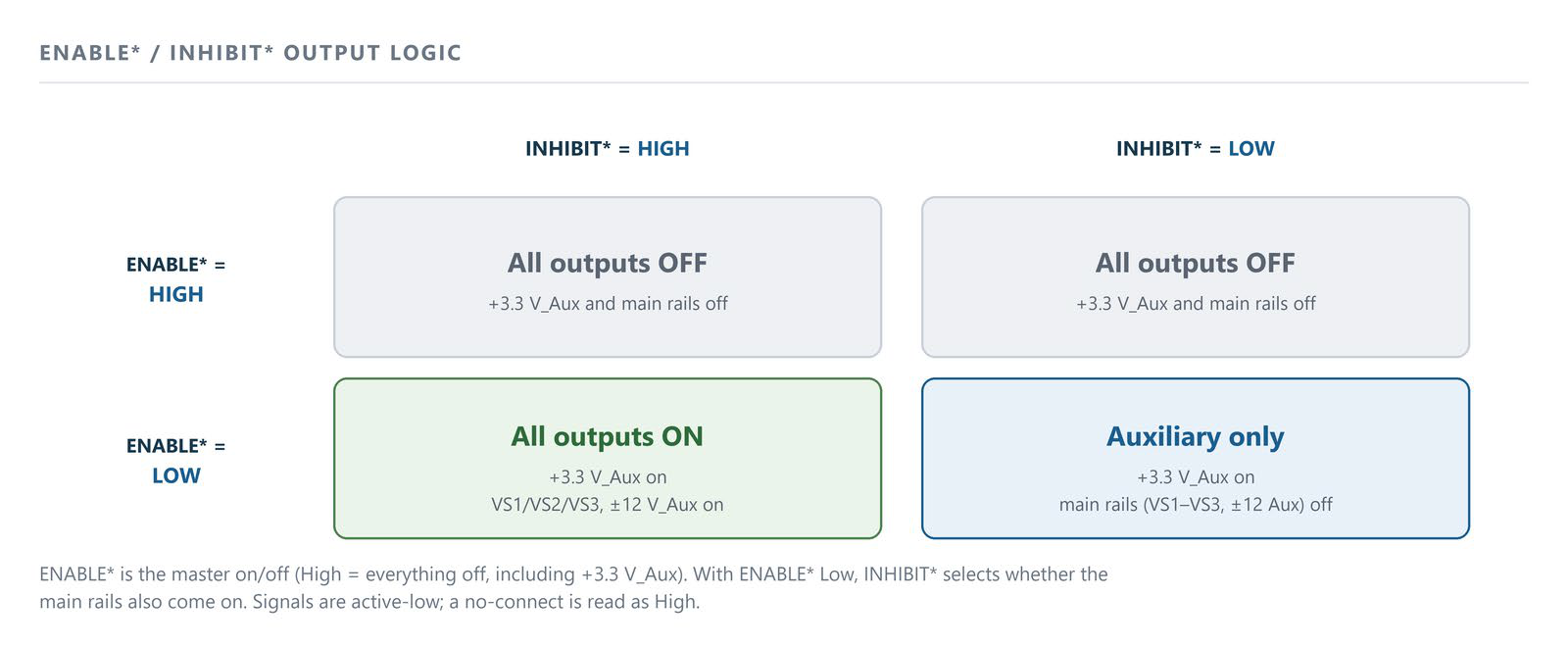
Figure 1. ENABLE*/INHIBIT* output logic. ENABLE* is the master on/off (High = everything off, including +3.3 V_Aux). With ENABLE* Low, INHIBIT* selects whether the main rails also come on. Both signals are active-low; a no-connect is read as High.
Power status table
| ENABLE* | INHIBIT* | +3.3 V_AUX | VS1 / VS2 / VS3, ±12 V_AUX |
|---|---|---|---|
| High | High | Off | Off |
| High | Low | Off | Off |
| Low | High | On | On |
| Low | Low | On | Off |
Signal levels and pin locations
The control inputs are TTL-compatible: an input below 0.8 VDC is read as a Low and an input above 2.0 VDC is read as a High. A no-connect is treated as a High.
On the NAI series of VPX power supplies, both signals appear on the VITA 62 P1 output connector: INHIBIT* on Pin C2, ENABLE* on Pin D2, and SIGNAL_RETURN on Pin D7. To use a mechanical switch on ENABLE*, tie Pin D2 to the SIGNAL_RETURN pin (D7); ENABLE* can also be driven directly by a logic output.
Application examples
- Controlled power-up — bring +3.3 V_Aux up first, then release the main rails by taking INHIBIT* High.
- Remote / backplane control — start, stop, or perform an emergency power-off from the system controller without switching the input supply.
- Logic-only checks — energize just the auxiliary rail for logic-level diagnostics or troubleshooting without powering the full payload.
See also
- The VBAT feature on NAI VPX power supplies — keeping +3.3 VDC_Aux (and therefore VBAT) alive with ENABLE*/INHIBIT*.
- Interpreting the Status LED on NAI VPX power supplies — a blinking green LED indicates the unit is disabled by the enable/inhibit control.
- IPMI Guide — the software (I2C) INHIBIT/ENABLE controls and the PRIORITY bit that selects between hardware and software control.
- CH1 Manual — Chassis Control Signals — defines the ENABLE* and INHIBIT* chassis control signals and describes how the chassis manager asserts INHIBIT* for power-down, power-cycle, and emergency shutdown.
- Power Products FAQ — ENABLE* / INHIBIT*