
Introduction
NAI VPX power supplies include a front-panel Status LED that provides an immediate indication of operating condition. By noting both the color and the pattern (steady or blinking), an operator can distinguish normal operation, a disabled state, loss of input power, and fault conditions. This application note explains each indication and provides a concise troubleshooting sequence for system bring-up and integration.
LED location
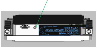
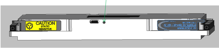
The multi-state LED is on the top edge of the module and is visible to the user when the power supply is plugged into the system backplane. The approximate location for the 3U and 6U power supplies is shown below.
Approximate LED location, 3U VPX power supply
Approximate LED location, 6U VPX power supply
Status LED quick reference
Use both color and pattern to interpret the indicator; color alone is not sufficient.
| LED indication | Power-supply condition |
|---|---|
| Off | Input voltage is low or absent. |
| Green (steady) | VOUT is within tolerance; all outputs are good. |
| Blinking green | The unit is disabled by the enable/inhibit control. |
| Red (steady) | A fault is present; indication follows FAIL* logic. |
| Blinking red | Over-voltage or over-temperature; all outputs are off. |
Key point
A green LED may indicate normal operation (steady) or a commanded-disabled state (blinking). Always distinguish the pattern.
Troubleshooting by indication
Use the applicable product datasheet for exact input-voltage limits, thermal limits, connector pin definitions, and control-signal requirements.
LED off — input voltage low or absent
Verify input power at the supply and confirm that it is within the specified input range. Inspect the input source and cabling. With system power removed and approved handling procedures followed, confirm that the supply is fully seated in the backplane and inspect the connector pins for damage.
Blinking green — unit disabled
Verify the enable/inhibit control state and confirm that the system has commanded the supply on. Check the relevant connector pin and control-signal polarity against the product datasheet and the system design. See INHIBIT* / ENABLE* control on NAI VPX power supplies for the control-input logic and pin locations.
Red (steady) — fault present
Because the LED follows the same logic as the FAIL* signal, check FAIL* at the system level. Inspect each output for an overload or downstream short, and compare the load on each output with the supply’s rated limits. For what drives FAIL*, see the Power Products FAQ; on supplies with the I2C management interface, the FAIL and OT bits of the status register in the IPMI Guide report the same conditions.
Blinking red — over-voltage or over-temperature
All outputs are off in this state. Determine which protection condition is present and correct its cause before returning the supply to service.
- Over-temperature: Confirm that ambient temperature is within the datasheet range and that airflow is unobstructed. For conduction-cooled installations, verify that the specified cooling surfaces are clean, flat, and properly mated.
- Over-voltage: Remove input power, allow the unit to shut down completely, and then restore power. If the indication returns, contact NAI support.
Getting support
If the Status LED continues to indicate a fault after these checks, contact NAI support. To speed diagnosis, provide:
- the supply part number and serial number;
- the LED color and whether it is steady or blinking;
- the measured input voltage and a summary of output loading; and
- the troubleshooting steps already completed and their results.