
Introduction
VBAT is an optional output defined by the VITA 62 power-supply and VITA 46 VPX baseline standards. Those standards allow VBAT to be sourced either from the power supply itself or from an energy-storage module such as a battery. On NAI VPX series power supplies, VBAT is sourced from the supply’s +3.3 VDC_Aux output; it is not backed by a battery. VBAT is a bussed signal on the VITA 46 backplane and is intended to power low-power devices (up to 1 A) such as a real-time clock or a processor held in sleep mode.
Why a dedicated VBAT line
VBAT provides the same 3.3 V rail as +3.3 VDC_Aux, but on a separate, dedicated line with its own over-current protection. The advantage over drawing from +3.3 VDC_Aux directly is isolation: an over-current event on the shared +3.3 VDC_Aux output does not disturb VBAT, so a low-power load that must stay alive (a clock or sleeping processor) keeps running.
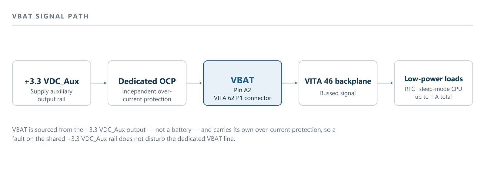
Figure 1. VBAT signal path. VBAT is sourced from the +3.3 VDC_Aux output (not a battery) and carries its own over-current protection, so a fault on the shared +3.3 VDC_Aux rail does not disturb the dedicated VBAT line.
Do not connect VBAT to a battery
In the broader VITA 62 utility set, VBAT is often used as battery-backed hold-up, keeping a real-time clock or CMOS settings alive after main power is removed. The NAI implementation is different: because VBAT is derived from the +3.3 VDC_Aux rail rather than a battery, it is available only while input power is applied. It is not hold-up power that survives loss of the main input.
For the same reason, VBAT should not be connected to a battery. VBAT is a driven output, not a battery input; a cell tied to it would simply drain back through the supply’s output circuitry when the supply is unpowered, discharging the battery. Use VBAT only to power low-power electronics, not to back up, charge, or maintain a battery.
Keeping +3.3 VDC_Aux alive with ENABLE* / INHIBIT*
The +3.3 VDC_Aux output, and therefore VBAT, can remain on while all other outputs are off, provided input power is still applied, by using the VITA 62 ENABLE* and INHIBIT* controls.
Pulling INHIBIT* low turns off VS1, VS2, VS3 and the ±12 VDC_Aux outputs. An input below 0.8 VDC is read as a low and an input above 2.0 VDC is read as a high; a no-connect is also read as a high. Together with ENABLE*, this signal sets the output power status of the supply. Applying a low to both ENABLE* and INHIBIT* leaves +3.3 VDC_Aux on while all other outputs stay off.
For the full description of the two control inputs, their pin locations, and the power status table for every combination of ENABLE* and INHIBIT*, see INHIBIT* / ENABLE* control on NAI VPX power supplies — power status table.
Pin location and availability
VBAT is a standard signal on NAI VPX series power supplies, located on Pin A2 of the VITA 62 P1 connector. It is present across the standard and SOSA-aligned output configurations; no ordering option is required to enable it.