SIU33 DATA SHEET
Click here for the SIU33 data sheet
INTRODUCTION
North Atlantic Industries’ (NAI) Sensor Interface Unit (SIU33) is a rugged base-plate conduction-cooled that takes advantage of NAI’s rugged conduction-cooled 3U cPCI multi-function I/O boards and power supply product architecture. The SIU33 provides a high density, compact data distribution system solution for I/O intensive and/or processing applications. The SIU33 supports full I/O control and communication over Ethernet. MIL-STD-1553, ARINC 429/575, Serial or CANBus interfaces are also available as primary interfaces when the boards are configured as such. PowerPC, Intel® Core™-i7, Intel ATOM™ or ARM Single Board Computer (SBC) processors can be added for a complete processing and I/O solution. The SIU33 is designed to support up to three NAI multi-function pre-configurable I/O boards, with or without processing, that support a wide variety of interface and communications function modules, all fitted/housed in a single rugged multi-board slot SIU system chassis, which is “delivered” pre-integrated and fully tested as a system.
Note
Since initial release of the SIU33 product line, the SIU33 housing was updated to include support for VPX (VITA 46) & OpenVPX (VITA 65) architecture SBC & I/O boards. The SIU33 can be configured to support VPX architecture for certain/select applications as/if applicable. Primary reference to cPCI will remain throughout this manual, but it is noted that certain details which may be specific to VPX are not highlighted in this general manual.
OBJECTIVES
This manual provides the user with basic hardware implementation and information regarding the operation and interface of the SIU33. Each SIU33 is fitted with either one to three 3U OpenVPX boards and a AC or DC power supply unit. Additional PSU option for “hold-up” power/time is available.
SCOPE
This manual only covers the operation of the SIU33 as a stand-alone I/O subsystem. This manual does not cover specific details relating to the operation of the specific I/O boards and function modules fitted within the SIU33. Please reference the board specific documentation for details regarding the board level configuration(s).
CONVENTIONS USED IN THIS MANUAL
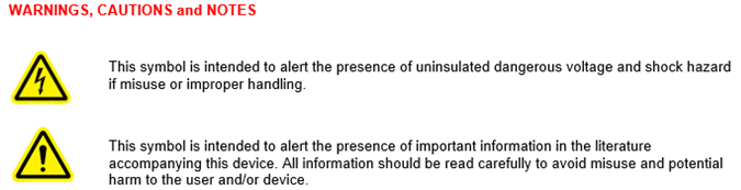
NOTE An operating procedure, practice, or condition, etc., that is essential to emphasize.
All numbers are expressed in decimal format unless otherwise noted.
GENERAL SAFETY NOTICES
The following general safety notices supplement the specific warnings and cautions appearing elsewhere in the manual. They are recommended precautions that must be understood and applied during operation and maintenance of the instrument covered herein.
Serious injury may result if personnel fail to observe safety precautions. Dependent on configuration, some modules (e.g. Synchro / Resolver or AC signal sources) can generate output signals with high voltages. Be careful not to contact high-voltage connections when installing, operating or maintaining this instrument.

The SIU33 is delivered as a standalone system. Besides removing the rear cover to access a board’s front panel I/O, if required, NAI recommends that the boards and power supply NOT be removed from the chassis.
REPAIR
DO NOT ATTEMPT REPAIR. Under no circumstances should repair of this instrument be attempted. All repairs to this chassis must be accomplished at the factory.
HIGH VOLTAGE

HIGH VOLTAGE may be used in the operation of this equipment.
INPUT POWER ALWAYS ON

Note
The design of the model SIU33 is such that input power is continuously supplied to internal circuits when connected to a main power source. To disconnect the SIU33 from external power, the external power source should first be de-energized. The power input cable can then be disconnected.
Website
SYSTEM SPECIFICATIONS AND DETAILS
Introduction
The model SIU33 is a next generation rugged systems chassis joining the NAI Sensor Interface Unit (SIU) system chassis family pedigree. The SIU35 is configured to support a wide variety of SBC and multifunction I/O boards that can be configured to support a variety of processing, communications and I/O functions that are supported under the NAI Configurable Open Systems Architecture ™ (COSA®) product families.
The SIU33 can function either as a centralized or distributed system. It can also be used to supplement existing legacy systems by easily adding sensor data acquisition as well as general I/O and communication interfaces without expensive legacy chassis and backplane redesign. It has been designed with rugged embedded industrial, military and aerospace applications in mind.
Leveraging NAI’s field-proven, unique modular architecture, the SIU33 supports standard 3U cPCI board-level compatible boards that can be fitted with a wide selection of different Intelligent I/O, motion simulation/measurement and communications functions such as:
| A/D Converter | D/A Converter | I/O TTL/CMOS | RTD | I/O Discrete |
| I/O Differential Transceiver | Synchro/Resolver LVDT/RVDT Measurement | Synchro/Resolver LVDT/RVDT Simulation | Strain Gauge | Encoder |
| Dual-Channel Dual Redundant BC/RT/MT MIL-STD-1553 | High-Speed Sync/Async RS232/422/423/485 | ARINC 429/575 | CAN bus | I/O Relay |
| AC Reference | Ethernet Switch | SSD/Flash | Check w/ NAI's factory or website for latest selection of available func ons | |
This approach provides unprecedented flexibility for supporting existing or new applications where there are specific interfacing requirements. Significant application benefits include:
-
Independent (pre-processed) I/O functionality targeted to specific data acquisition/control areas
-
Additional capabilities, technology insertion and sensor interfacing to existing fielded applications
-
Minimal integration risk based on current field-proven, deployed technologies
Specifications
The SIU33 is designed to meet the following general product specifications and is provided as a reference. Actual configuration and usage may affect size, weight and power (SWaP) specifications. Please contact NAI for discerning/defining SWaP considerations regarding specific program configurations. See additional details herein.
General
SIU33 General SWaP Specifications
| Input Voltage: | Standard/Default: DC: 18 to 36 VDC (28 VDC nominal) |
|---|---|
| Power (Base unit): | ~10 W (PSU efficiency, at 100W load) @ 28 VDC nominal Then, add the power calculated for the configuration specific boards module(s) power (see separate specific boards and module(s) specifications). I/O Signal GND reference is isolated from main power source return and chassis. |
| Power/Heat Dissipation: | Conduction Cooled (CC): ~75 watts (maximum) when properly mounted to a cold plate, which must be maintained at a temperature not to exceed 71°C. NOTE: The total SIU33 power dissipation is dependent on the configuration of the boards and function module types fixed in the SIU33. Environmental and other operating characteristic variable considerations should be considered. |
| Temperature, Operating: | -40°C to 71°C Conduction cooled: As measured at primary thermal transfer interface. |
| Temperature, Storage: | -55°C to 105°C |
| Size: | Height: ~4.8” (122 mm) Depth: ~8.8” (224 mm) Width: ~4.7” (119 mm) |
| Weight: | The weight of an SIU33 system is dependent on the configuration. The approximate weight of the SIU33 is based on the selection of the PSU, boards and functional module(s). The approximate weight of a configured SIU33 is: ~5.5 lbs. unpopulated - Chassis/backplane/rigid flex & connector boards (conduction cooled) ~1.4 lbs. for PSU ~1.25 lbs. for each additional fully function module populated board or SBC ~10.7 lbs. fully populated |
UNPACKING AND INSPECTION
Unpacking
The SIU33 packing materials were designed specifically for transport protection of the SIU33. When receiving the shipment container, inspect packaging for any evidence of physical damage. If damage is evident, it is recommended that the carrier agent is present when opening the shipping container. It is further recommended that all packing material is retained in the event the SIU33 needs to be shipped elsewhere.
System/Chassis Identification
An identification label, indicating part number, unique serial number and Ethernet PHY MACs / default IP address(es) is affixed to the system chassis.
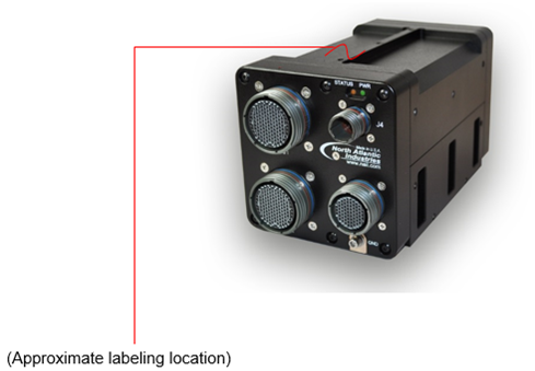 Figure 1. SIU33 Unit Identification Label Location
Label information provided:
 Unit Level Part Number

 Unit Level Serial Number

 Unit Level Date Code
Also, typically provided with:
 Slot/Board configuration(s) as applicable

 Slot/Board serial numbers and D/C

 Slot/Board IP address / MAC address (if applicable)
Special labeling requirements are also considered (i.e. UID matrix, customer part number, etc.). Contact factory for special labeling requirements.
Inspection
Inspect the chassis and connectors to ensure that they were not damaged during transit.
MECHANICAL INTERFACE
Mechanical Description
The SIU33 is a rugged, aluminum, conduction-cooled chassis that requires proper mounting to a cold-plate or surface that is maintained at 71°C or less. Three mounting holes are provided along each side of the SIU33. Please see the outline and interface drawings below. Note that hardware is not supplied
Mounting Requirements
Refer to SIU33 Outline and Installation Drawing (OID) for details on mounting and installing the SIU33. It is available for download from NAI’s website. The SIU33 is conduction cooled and must be mounted in accordance with the drawing. The OID provides recommended hardware, torque, cold-plate flatness and surface finish specifications, and thermal conductivity requirements.
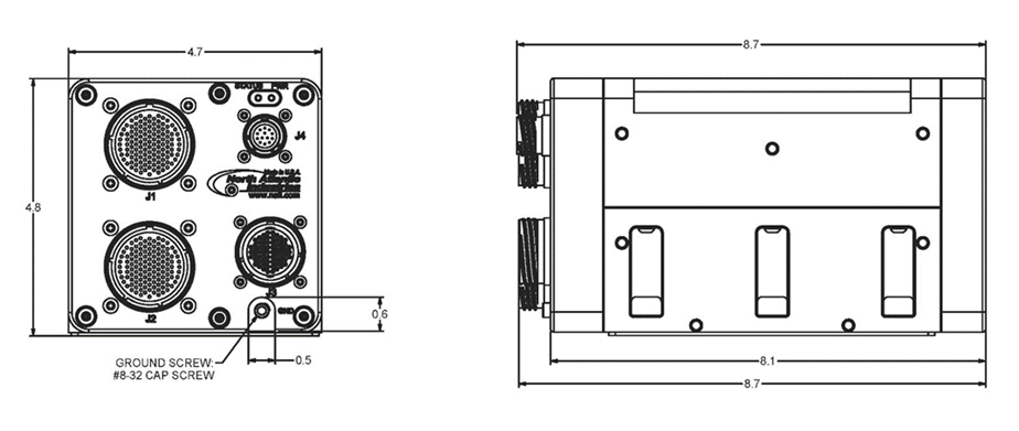 Figure 2. SIU33 Conduction Cooled Outline Dimensions (Reference Only)
Chassis (Earth) GND
Chassis ground point threaded insert location is on the connector face (front) of the SIU33 as shown.
caution image here Chassis ground location is on the connector face (front) of the SIU33 as shown.
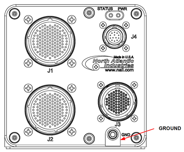 Figure 3. SIU33 Chassis GND location
Finish
Unless otherwise specified, the following standard finish, or equivalent per NAI process requirements applies:
-
PRE-TREATMENT: CHEMICAL FILM COATING IAW MIL-DTL-5541, TYPE II, CLASS 3, ALL OVER.
-
PAINT PRIMER COAT: IAW-MIL-PRF-23377, TYPE II, CLASS 2, WITH A 0.9MIL MINIMUM DRY FILM THICKNESS TO EXTERIOR SURFACES SHOWN IN PAINT MASKING FIGURES.
-
PAINT FINISH COAT: APPLY MEDIUM TEXTURE USING PER MIL-PRF-85285, TYPE I, CLASS 2, SEMI-GLOSS BLACK WITH A DRY FILM THICKNESS OF 0.0008 TO 0.0012 TO EXTERIOR SURFACES.
-
FINISH NOTES 2 AND 3 OMITTED FROM THERMAL INTERFACE SURFACE INDICATED & FROM ALL HARDWARE.
CONNECTOR DESIGNATIONS, LOCATIONS & DESCRIPTIONS
The Power, I/O Interface and Ethernet connectors are accessible from the SIU33 front housing panel. The J4 Power Connector shown is the 13-pin, 28 VDC connector. See the Input Power Connector (J4) section that follows for the other options.
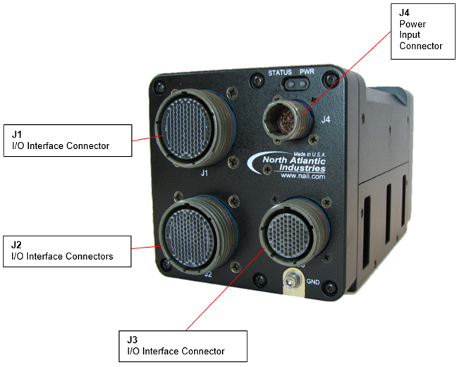 Figure 4. SIU33 (Front Panel Connector Placement)
| REF. DES. | KEY | MANUFACTURER / MIL-DTL SPEC. (or Equiv.) | P/N | MATE P/N |
|---|---|---|---|---|
| J1 | N | AMPHENOL | AMP 88-569779-35SN | D38999/26WJ35P |
| J2 | A | AMPHENOL | AMP 88-569779-35SA | D38999/26WJ35PA |
| J3 | N | AMPHENOL | AMP 88-569776-35S | D38999/26WF35P |
| J4 | N | MIL-DTL-D38999 Type | AMP 88-569772-35PN | D38999/26WB35SN |
CONNECTOR DETAILS AND PINOUTS
Generic pinout. See module I/O section or contact factory regarding any special module I/O configuration.
J4, Primary Power Connector
Primary input power is supported on the SIU33 via the J4 connector. There are three input power options for the SIU33: 28 VDC, 115/230 1ø VAC or 270 VDC. Two unique power connectors are used; one for the 28 VDC input and one for the 115/230 1ø VAC or 270 VDC input.
28 VDC Input Connector
If 28 VDC is specified:
Part Number: TVP02RW-11-35PN, (w/ 10,000 pf conn filtering)
Equivalent to MIL-DTL-D38999 Series III and insert arrangement IAW MIL-STD-1560: Shell size 11-35 (Insert 35), “N” (Normal) key, 13 pins.
Input Mating Connector: D38999/26WB35SN or equivalent
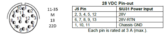 Figure 5. 28 VDC Pin Insert Arrangement, Front View
115/230 1ø VAC and 270 VDC Connector
If 115/230 1ø VAC and 270 VDC is specified:
Part Number: H9300W11-05PN110Y, (w/ 10,000 pf conn filtering)
Equivalent to MIL-DTL-D38999 Series III and insert arrangement IAW MIL-STD-1560: Shell size 11-5 (Insert 5), “N” (Normal) key, 5 pins.
Input Mating Connector: D38999/26W115SN or equivalent
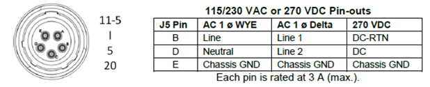 Figure 6. 115/230 1ø VAC or 270 VDC Pin Insert Arrangement, Front View
I/O Connectors (J1 to J3) and SLOT Designations
Connectors J1 to J3 route all the I/O from the three cPCI boards within the SIU33. The I/O pins from the cPCI Slot-X_P2 connectors of the cPCI cards are routed through the backplane to the SIU33 front panel connector. The I/O pin-out information for the J1 to J3 is defined by the configuration of the cPCI boards and function modules fitted to the cPCI boards.
Note
The SIU33 was originally introduced as a cPCI board support system. It has since evolved in supporting VPX board configurations. For configurations supporting VPX boards, the J3 I/O connector is replaced with a 128-pin 25-35F sell/insert B-key connector. References to follow or currently for the cPCI board support systems only. Please contact the factory for additional details supporting VPX board configurations if/as applicable.
| Jx Designation | SIU33 Connector MFG. P/N (or equivalent) | Board # | NAI Conn P/N | Key |
|---|---|---|---|---|
| J1 | AMP 88-569779-35S | Slot-1 | 05-0270 | key (N) |
| J2 | AMP 88-569779-35SA | Slot-2 | 05-0271 | key (A) |
| J3 | AMP 88-569779-35S | Slot-3 | 05-0274 | key (N) (see NOTE above) |
| (J4) | AMP 88-569772-35PN | [ PSU (Slot-4) ] | (05-279) | key (N) |
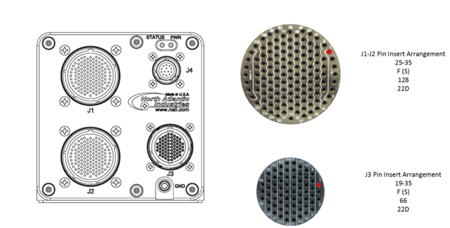 Figure 7. SIU33 Assembled, Front Panel View
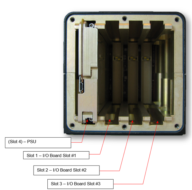 Figure 8. SIU33 SLOT Designation - SIU33 Rear Access Panel Removed
Mating Connector Information
Mating Connector Kit: NAI P/N: SIU33-CONN-KIT
Available as an optional separate line item. The mating connector kit includes 1 each (or equivalent):
| J1 Mate | NAI P/N: 05-0280-COM |
| HD38999 Type III / D38999/26WJ35PN / EN, 128-pin, N-Key | |
| J2 Mate | NAI P/N : 05-0281-COM |
| HD38999 Type III / D38999/26WJ35PA / EN, 128-pin, A-Key | |
| J3 Mate | NAI P/N : 05-0284-COM |
| HD38999 Type III / D38999/26WF35PN / EN, 66-pin, N-Key | |
| J4 Mate | NAI P/N : 05-0289-COM |
| D38999/26WB35SN / OD, 13-pin, N-Key |
POWER-UP AND BASIC OPERATIONS
Panel LEDs & Functions
Front Panel Power & Status LED Indicators
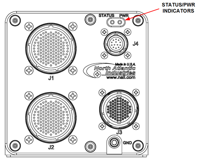 Figure 9. SIU33 Front View (Status LEDs Location)
| STATUS | Indication | POWER | Indication |
|---|---|---|---|
| [extinguished] | Default | [extinguished] | OFF / Power Fault |
| GRN | (Status 1) | GRN | ON / Power OK |
| RED | (Status 2) | x | x |
Status LED
- Single Board Computer (SBC) inserted in Slot 1, for example: 75PPC1.
A. If the primary processor and associated peripherals are powered on and configuration status is OK, AND, the board configured I/O function module(s) are reported as configuration status “OK”, then the status LED will illuminate GRN (typically, within 10 seconds of SIU33 power-on). B. If the primary processor and associated peripherals are powered on and configuration status is OK, AND, the board configured I/O function module(s) are reported as configuration status NOT “OK”, then the status LED will illuminate RED (typically, within 10 seconds of SIU33 power-on). C. If the primary processor and associated peripherals are powered on but the configuration status is NOT “OK”, then the status LED will remain extinguished (typically, after 10 seconds of SIU33 power-on).
-
Non-processor card inserted in Slot 1, for example: 75G5.
NONE (STATUS LED is extinguished).
Power LED
Provided from power supply unit (PSU) or strapped accordingly - SIU35 power “ON” indication
Basic Operations
The SIU33 is delivered as a tested unit. All pins and operation have been verified. It is recommended that Power and Ethernet connections be made to verify operation of the boards fitted within the SIU33 by making use of NAI’s Embedded Soft Panel based GUI sample application that can be utilized as a board level “exercising” tool (if the SIU33 card configuration supports). The example process below describes the use of NAI’s Ethernet communications software tool.
After applying appropriate power to the SIU33, connect a host computer (laptop or similar running Windows or Linux), to the appropriate Ethernet enabled/configured board (configured/populated in slot 1) Port A or Port B. The selection of Ethernet Port A or B is dependent on Slot-1 cPCI board configuration.
Note
Ethernet port assignments, MAC address, and factory default IP address are indicated on the chassis label
For detailed supplement, please visit the NAI web-site specific product page(s).
QUALIFICATION
The SIU33 has been designed to meet the following general specifications. Cooling type, size, weight, power and environmental characteristics may affect the program requirements and the specifications as applied. Contact factory for the SIU33 Qualification Test status.
Environmental
Environmental Qualification Testing Specifications
| Environmental MIL-STD-810 (1) (unless otherwise specified) | ||||||
| No. | Description | Procedure | Cycles | Table | Figure | Comments |
| 514 | Random Vibe | Method 514.6, 0.1g2/Hz from 100 to 1K Hz., -3dB octave 5-100 Hz and -6dB 1K-2K Hz,(operational) | ||||
| 514 | Sinusoidal Vibe | TBD | ||||
| 501 | Temp (High) | 3 | 3 periods (@ 4 hrs. ea.) within 24 hrs. cycle at 71 ºC baseplate | |||
| 502 | Temp (Low) | 1 | 3 periods (@ 4 hrs. ea.) within 24 hrs. cycle at -40 ºC baseplate | |||
| 503 | Temp (Shock) | 3 | 3 x 1 hr. each hot & cold cycle | |||
| 507 | Humidity | II | 10 | 507.5-7 | 507.5-IX | Cyclic high humidity (Cycle B2) |
| 500 | Altitude (50K) | II | 1 | n/a | n/a | 10m/s to 50,000ft for 1 hr. |
| 513 | Acceleration | II | 1 | 513.6-II | n/a | Carrier-based Aircraft (18g's max) |
| 516 | Shock - Operating | I | 3 | 516.6-I | n/a | 40g's, 1 min each x 6 axis |
| 516 | Shock - Crash | V | 3 | 516.6-I | n/a | 75g's, 1 min each x 6 axis |
| Ingress Protection IEC 60529 (1, **2)** | ||||||
| No. | Description | Procedure | Cycles | Table | Figure | Comments |
| IP54 | Dust Protection | (other - pending characterization / contact factory) | ||||
| IP54 | Water Splashing | (other - pending characterization / contact factory) | ||||
| IP65 | Dust Tight | (other - pending characterization / contact factory) | ||||
| IP65 | Water Jets | (other - pending characterization / contact factory) | ||||
EMI/EMC Specifications
EMI/EMC Qualification Testing Specifications
| EMC / MIL-STD-461 (1, 2) (unless otherwise specified)* | ||
| MIL-STD-461F | Method/Curve/Procedure | Comments |
| CE102 | Conducted, Emissions, Power Leads, 10K - 10M Hz | |
| CS101 | Conducted, Susceptibility, Power Leads, 30 - 150K Hz | |
| CS106 | Conducted, Susceptibility, Power Leads | |
| CS114 | Conducted, Susceptibility, Power Leads, 10K - 10M Hz | |
| CS115 | Conducted, Susceptibility, Bulk Injection | |
| CS116 | Conducted, Susceptibility, SIN Transient 10K - 100M Hz | |
| RE101 | Radiated, Emissions, Magnetic Field, 30 - 100K Hz | |
| RE102 | Radiated, Emissions, Electric Field, 10K - 1.25G Hz | |
| RS101 | Radiated, Susceptibility, Magnetic Field, 30 - 100K Hz | |
| RS103 | Radiated, Susceptibility, Electric Field, 2M - 18G Hz | |
Notes:
*1 - Designed to meet / Generic Test Reports Available
*2 - Utilizing proper shielded cables and system grounding practices
HEAT DISSIPATION
The SIU33 is capable of dissipating up to a total of 125 Watts when properly mounted. Generally, the conduction cooled version thermal interface must be maintained at a temperature not to exceed 71°C. Other operating and environmental factors and variable must be considered when specifying for a higher-level system platform integration. The total SIU33 power dissipation is dependent on the configuration of the cPCI boards and power supply fitted in the SIU33.
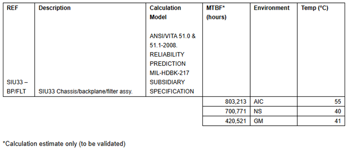
RELIABILITY
The reliability of the SIU33 is dependent on the configuration of the OpenVPX boards and power supply fitted within it. The Mean Time between Failures is for the SIU33 configured with chassis, backplane, EMI Filter and connectors.
MTBF
The Mean Time between Failures is configuration, environment and temperature dependent. Please contact factory regarding calculations based on the specific configuration and program requirements.
SIGNAL PIN-OUTS
The following pinouts provides a general use guideline as an example, only. Pinout routing will be dependent on card type/configuration for optimal I/O usage. Consult NAI factory for assistance in determining specific configuration signal definitions as applicable.
Pin-Out / General / I/O Connector (Slot 1)
| SLOT 1 I/O | ||||
|---|---|---|---|---|
| J1 | J2 | J3 | GENERIC I/O | EXAMPLE: 75G5-Z00Z00Z001WX4X (MASTER w/ Two Gig-E) |
| 5 | SLOT1-M1-D1 | MOD1-DATIO1 | ||
| 13 | SLOT1-M1-D2 | MOD1-DATIO2 | ||
| 6 | SLOT1-M1-D3 | MOD1-DATIO3 | ||
| 7 | SLOT1-M1-D4 | MOD1-DATIO4 | ||
| 12 | SLOT1-M1-D5 | MOD1-DATIO5 | ||
| 20 | SLOT1-M1-D6 | MOD1-DATIO6 | ||
| 14 | SLOT1-M1-D7 | MOD1-DATIO7 | ||
| 24 | SLOT1-M1-D8 | MOD1-DATIO8 | ||
| 21 | SLOT1-M1-D9 | MOD1-DATIO9 | ||
| 32 | SLOT1-M1-D10 | MOD1-DATIO10 | ||
| 22 | SLOT1-M1-D11 | MOD1-DATIO11 | ||
| 33 | SLOT1-M1-D12 | MOD1-DATIO12 | ||
| 23 | SLOT1-M1-D13 | MOD1-DATIO13 | ||
| 34 | SLOT1-M1-D14 | MOD1-DATIO14 | ||
| 35 | SLOT1-M1-D15 | MOD1-DATIO15 | ||
| 47 | SLOT1-M1-D16 | MOD1-DATIO16 | ||
| 30 | SLOT1-M1-D17 | MOD1-DATIO17 | ||
| 42 | SLOT1-M1-D18 | MOD1-DATIO18 | ||
| 31 | SLOT1-M1-D19 | MOD1-DATIO19 | ||
| 43 | SLOT1-M1-D20 | MOD1-DATIO20 | ||
| 44 | SLOT1-M1-D21 | MOD1-DATIO21 | ||
| 56 | SLOT1-M1-D22 | MOD1-DATIO22 | ||
| 45 | SLOT1-M1-D23 | MOD1-DATIO23 | ||
| 57 | SLOT1-M1-D24 | MOD1-DATIO24 | ||
| 46 | SLOT1-M1-D25 | MOD1-DATIO25 | ||
| 58 | SLOT1-M1-D26 | MOD1-DATIO26 | ||
| 53 | SLOT1-M1-D27 | MOD1-DATIO27 | ||
| 65 | SLOT1-M1-D28 | MOD1-DATIO28 | ||
| 54 | SLOT1-M1-D29 | MOD1-DATIO29 | ||
| 66 | SLOT1-M1-D30 | MOD1-DATIO30 | ||
| 55 | SLOT1-M1-D31 | MOD1-DATIO31 | ||
| 67 | SLOT1-M1-D32 | MOD1-DATIO32 | ||
| 5 | SLOT1-M2-D1 | MOD2-DATIO1 | ||
| 13 | SLOT1-M2-D2 | MOD2-DATIO2 | ||
| 6 | SLOT1-M2-D3 | MOD2-DATIO3 | ||
| 7 | SLOT1-M2-D4 | MOD2-DATIO4 | ||
| 12 | SLOT1-M2-D5 | MOD2-DATIO5 | ||
| 20 | SLOT1-M2-D6 | MOD2-DATIO6 | ||
| 14 | SLOT1-M2-D7 | MOD2-DATIO7 | ||
| 24 | SLOT1-M2-D8 | MOD2-DATIO8 | ||
| 21 | SLOT1-M2-D9 | MOD2-DATIO9 | ||
| 32 | SLOT1-M2-D10 | MOD2-DATIO10 | ||
| 22 | SLOT1-M2-D11 | MOD2-DATIO11 | ||
| 33 | SLOT1-M2-D12 | MOD2-DATIO12 | ||
| 23 | SLOT1-M2-D13 | MOD2-DATIO13 | ||
| 34 | SLOT1-M2-D14 | MOD2-DATIO14 | ||
| 35 | SLOT1-M2-D15 | MOD2-DATIO15 | ||
| 47 | SLOT1-M2-D16 | MOD2-DATIO16 | ||
| 30 | SLOT1-M2-D17 | MOD2-DATIO17 | ||
| 42 | SLOT1-M2-D18 | MOD2-DATIO18 | ||
| 31 | SLOT1-M2-D19 | MOD2-DATIO19 | ||
| 43 | SLOT1-M2-D20 | MOD2-DATIO20 | ||
| 44 | SLOT1-M2-D21 | MOD2-DATIO21 | ||
| 56 | SLOT1-M2-D22 | MOD2-DATIO22 | ||
| 45 | SLOT1-M2-D23 | MOD2-DATIO23 | ||
| 57 | SLOT1-M2-D24 | MOD2-DATIO24 | ||
| 13 | SLOT1-M3-D1 | MOD3-DATIO1 | ||
| 7 | SLOT1-M3-D2 | MOD3-DATIO2 | ||
| 14 | SLOT1-M3-D3 | MOD3-DATIO3 | ||
| 8 | SLOT1-M3-D4 | MOD3-DATIO4 | ||
| 29 | SLOT1-M3-D5 | MOD3-DATIO5 | ||
| 21 | SLOT1-M3-D6 | MOD3-DATIO6 | ||
| 30 | SLOT1-M3-D7 | MOD3-DATIO7 | ||
| 3 | SLOT1-M3-D8 | MOD3-DATIO8 | ||
| 11 | SLOT1-M3-D9 | MOD3-DATIO9 | ||
| 5 | SLOT1-M3-D10 | MOD3-DATIO10 | ||
| 4 | SLOT1-M3-D11 | MOD3-DATIO11 | ||
| 6 | SLOT1-M3-D12 | MOD3-DATIO12 | ||
| 31 | SLOT1-M3-D13 | MOD3-DATIO13 | ||
| 9 | SLOT1-M3-D14 | MOD3-DATIO14 | ||
| 32 | SLOT1-M3-D15 | MOD3-DATIO15 | ||
| 16 | SLOT1-M3-D16 | MOD3-DATIO16 | ||
| 42 | SLOT1-M3-D17 | MOD3-DATIO17 | ||
| 33 | SLOT1-M3-D18 | MOD3-DATIO18 | ||
| 22 | SLOT1-M3-D19 | MOD3-DATIO19 | ||
| 15 | SLOT1-M3-D20 | MOD3-DATIO20 | ||
| 23 | SLOT1-M3-D21 | MOD3-DATIO21 | ||
| 24 | SLOT1-M3-D22 | MOD3-DATIO22 | ||
| 12 | SLOT1-M3-D23 | MOD3-DATIO23 | ||
| 2 | SLOT1-M3-D24 | MOD3-DATIO24 | ||
| 35 | SLOT1-ETH1-R-TP0- | ETH1-TP0- | ||
| 34 | SLOT1-ETH1-R-TP0+ | ETH1-TP0+ | ||
| 43 | SLOT1-ETH1-R-TP1+ | ETH1-TP1+ | ||
| 44 | SLOT1-ETH1-R-TP1- | ETH1-TP1- | ||
| 52 | SLOT1-ETH1-R-TP2- | ETH1-TP2- | ||
| 51 | SLOT1-ETH1-R-TP2+ | ETH1-TP2+ | ||
| 59 | SLOT1-ETH1-R-TP3- | ETH1-TP3- | ||
| 58 | SLOT1-ETH1-R-TP3+ | ETH1-TP3+ | ||
| 36 | SLOT1-ETH2-R-TP0+ | ETH2-TP0+ | ||
| 37 | SLOT1-ETH2-R-TP0- | ETH2-TP0- | ||
| 46 | SLOT1-ETH2-R-TP1- | ETH2-TP1- | ||
| 45 | SLOT1-ETH2-R-TP1+ | ETH2-TP1+ | ||
| 54 | SLOT1-ETH2-R-TP2- | ETH2-TP2- | ||
| 53 | SLOT1-ETH2-R-TP2+ | ETH2-TP2+ | ||
| 60 | SLOT1-ETH2-R-TP3- | ETH2-TP3- | ||
| 64 | SLOT1-ETH2-R-TP3+ | ETH2-TP3+ | ||
| 1 | DEBUG (I2C Clock) | N/C | ||
| 20 | DEBUG (I2C Data) | N/C | ||
| 40 | DEBUG (cPCI-PRSTn) | N/C | ||
| 10 | DEBUG (HDW WP) | N/C | ||
| 28 | Serial | SER-TXD1 | ||
| 27 | Serial | SER-RXD1 | ||
| 19 | Serial | SER-GND | ||
| 18 | DEBUG (RTC_STDBY) | N/C |
Pin-Out / General / I/O Connector (Slot 2)
| SLOT 2 I/O | ||||
|---|---|---|---|---|
| J1 | J2 | J3 | GENERIC I/O | EXAMPLE: 75G5-Z00Z00Z000WX0X |
| J1-48 | SLOT2-M1-D1 | MOD1-DATIO1 | ||
| J1-59 | SLOT2-M1-D2 | MOD1-DATIO2 | ||
| J1-49 | SLOT2-M1-D3 | MOD1-DATIO3 | ||
| J1-60 | SLOT2-M1-D4 | MOD1-DATIO4 | ||
| J1-71 | SLOT2-M1-D5 | MOD1-DATIO5 | ||
| J1-82 | SLOT2-M1-D6 | MOD1-DATIO6 | ||
| J1-72 | SLOT2-M1-D7 | MOD1-DATIO7 | ||
| J1-83 | SLOT2-M1-D8 | MOD1-DATIO8 | ||
| J1-84 | SLOT2-M1-D9 | MOD1-DATIO9 | ||
| J1-95 | SLOT2-M1-D10 | MOD1-DATIO10 | ||
| J1-74 | SLOT2-M1-D11 | MOD1-DATIO11 | ||
| J1-85 | SLOT2-M1-D12 | MOD1-DATIO12 | ||
| J1-75 | SLOT2-M1-D13 | MOD1-DATIO13 | ||
| J1-86 | SLOT2-M1-D14 | MOD1-DATIO14 | ||
| J1-76 | SLOT2-M1-D15 | MOD1-DATIO15 | ||
| J1-87 | SLOT2-M1-D16 | MOD1-DATIO16 | ||
| J1-94 | SLOT2-M1-D17 | MOD1-DATIO17 | ||
| J1-105 | SLOT2-M1-D18 | MOD1-DATIO18 | ||
| J1-96 | SLOT2-M1-D19 | MOD1-DATIO19 | ||
| J1-106 | SLOT2-M1-D20 | MOD1-DATIO20 | ||
| J1-97 | SLOT2-M1-D21 | MOD1-DATIO21 | ||
| J1-107 | SLOT2-M1-D22 | MOD1-DATIO22 | ||
| J1-98 | SLOT2-M1-D23 | MOD1-DATIO23 | ||
| J1-108 | SLOT2-M1-D24 | MOD1-DATIO24 | ||
| J1-99 | SLOT2-M1-D25 | MOD1-DATIO25 | ||
| J1-109 | SLOT2-M1-D26 | MOD1-DATIO26 | ||
| J1-115 | SLOT2-M1-D27 | MOD1-DATIO27 | ||
| J1-122 | SLOT2-M1-D28 | MOD1-DATIO28 | ||
| J1-116 | SLOT2-M1-D29 | MOD1-DATIO29 | ||
| J1-123 | SLOT2-M1-D30 | MOD1-DATIO30 | ||
| J1-117 | SLOT2-M1-D31 | MOD1-DATIO31 | ||
| J1-124 | SLOT2-M1-D32 | MOD1-DATIO32 | ||
| J1-68 | SLOT2-M2-D1 | MOD2-DATIO1 | ||
| J1-69 | SLOT2-M2-D2 | MOD2-DATIO2 | ||
| J1-70 | SLOT2-M2-D3 | MOD2-DATIO3 | ||
| J1-81 | SLOT2-M2-D4 | MOD2-DATIO4 | ||
| J1-77 | SLOT2-M2-D5 | MOD2-DATIO5 | ||
| J1-88 | SLOT2-M2-D6 | MOD2-DATIO6 | ||
| J1-78 | SLOT2-M2-D7 | MOD2-DATIO7 | ||
| J1-89 | SLOT2-M2-D8 | MOD2-DATIO8 | ||
| J1-79 | SLOT2-M2-D9 | MOD2-DATIO9 | ||
| J1-90 | SLOT2-M2-D10 | MOD2-DATIO10 | ||
| J1-80 | SLOT2-M2-D11 | MOD2-DATIO11 | ||
| J1-91 | SLOT2-M2-D12 | MOD2-DATIO12 | ||
| J1-92 | SLOT2-M2-D13 | MOD2-DATIO13 | ||
| J1-103 | SLOT2-M2-D14 | MOD2-DATIO14 | ||
| J1-93 | SLOT2-M2-D15 | MOD2-DATIO15 | ||
| J1-104 | SLOT2-M2-D16 | MOD2-DATIO16 | ||
| J1-100 | SLOT2-M2-D17 | MOD2-DATIO17 | ||
| J1-111 | SLOT2-M2-D18 | MOD2-DATIO18 | ||
| J1-101 | SLOT2-M2-D19 | MOD2-DATIO19 | ||
| J1-112 | SLOT2-M2-D20 | MOD2-DATIO20 | ||
| J1-102 | SLOT2-M2-D21 | MOD2-DATIO21 | ||
| J1-113 | SLOT2-M2-D22 | MOD2-DATIO22 | ||
| J1-110 | SLOT2-M2-D23 | MOD2-DATIO23 | ||
| J1-119 | SLOT2-M2-D24 | MOD2-DATIO24 | ||
| J1-114 | SLOT2-M2-D25 | MOD2-DATIO25 | ||
| J1-121 | SLOT2-M2-D26 | MOD2-DATIO26 | ||
| J1-118 | SLOT2-M2-D27 | MOD2-DATIO27 | ||
| J1-125 | SLOT2-M2-D28 | MOD2-DATIO28 | ||
| J1-120 | SLOT2-M2-D29 | MOD2-DATIO29 | ||
| J1-126 | SLOT2-M2-D30 | MOD2-DATIO30 | ||
| J1-127 | SLOT2-M2-D31 | MOD2-DATIO31 | ||
| J1-128 | SLOT2-M2-D32 | MOD2-DATIO32 | ||
| J1-1 | SLOT2-M3-D1 | MOD3-DATIO1 | ||
| J1-2 | SLOT2-M3-D2 | MOD3-DATIO2 | ||
| J1-3 | SLOT2-M3-D3 | MOD3-DATIO3 | ||
| J1-4 | SLOT2-M3-D4 | MOD3-DATIO4 | ||
| J1-8 | SLOT2-M3-D5 | MOD3-DATIO5 | ||
| J1-16 | SLOT2-M3-D6 | MOD3-DATIO6 | ||
| J1-9 | SLOT2-M3-D7 | MOD3-DATIO7 | ||
| J1-17 | SLOT2-M3-D8 | MOD3-DATIO8 | ||
| J1-10 | SLOT2-M3-D9 | MOD3-DATIO9 | ||
| J1-18 | SLOT2-M3-D10 | MOD3-DATIO10 | ||
| J1-11 | SLOT2-M3-D11 | MOD3-DATIO11 | ||
| J1-19 | SLOT2-M3-D12 | MOD3-DATIO12 | ||
| J1-15 | SLOT2-M3-D13 | MOD3-DATIO13 | ||
| J1-25 | SLOT2-M3-D14 | MOD3-DATIO14 | ||
| J1-26 | SLOT2-M3-D15 | MOD3-DATIO15 | ||
| J1-38 | SLOT2-M3-D16 | MOD3-DATIO16 | ||
| J1-27 | SLOT2-M3-D17 | MOD3-DATIO17 | ||
| J1-39 | SLOT2-M3-D18 | MOD3-DATIO18 | ||
| J1-28 | SLOT2-M3-D19 | MOD3-DATIO19 | ||
| J1-40 | SLOT2-M3-D20 | MOD3-DATIO20 | ||
| J1-29 | SLOT2-M3-D21 | MOD3-DATIO21 | ||
| J1-41 | SLOT2-M3-D22 | MOD3-DATIO22 | ||
| J1-36 | SLOT2-M3-D23 | MOD3-DATIO23 | ||
| J1-37 | SLOT2-M3-D24 | MOD3-DATIO24 | ||
| J1-50 | SLOT2-M3-D25 | MOD3-DATIO25 | ||
| J1-62 | SLOT2-M3-D26 | MOD3-DATIO26 | ||
| J1-51 | SLOT2-M3-D27 | MOD3-DATIO27 | ||
| J1-63 | SLOT2-M3-D28 | MOD3-DATIO28 | ||
| J1-52 | SLOT2-M3-D29 | MOD3-DATIO29 | ||
| J1-64 | SLOT2-M3-D30 | MOD3-DATIO30 | ||
| J1-61 | SLOT2-M3-D31 | MOD3-DATIO31 | ||
| J1-73 | SLOT2-M3-D32 | MOD3-DATIO32 |
Pin-Out / General / I/O Connector (Slot 3)
| SLOT 3 I/O | ||||
|---|---|---|---|---|
| J1 | J2 | J3 | GENERIC I/O | 75G5-Z00Z00Z000WX0X |
| J2-48 | SLOT3-M1-D1 | MOD1-DATIO1 | ||
| J2-59 | SLOT3-M1-D2 | MOD1-DATIO2 | ||
| J2-49 | SLOT3-M1-D3 | MOD1-DATIO3 | ||
| J2-60 | SLOT3-M1-D4 | MOD1-DATIO4 | ||
| J2-71 | SLOT3-M1-D5 | MOD1-DATIO5 | ||
| J2-82 | SLOT3-M1-D6 | MOD1-DATIO6 | ||
| J2-72 | SLOT3-M1-D7 | MOD1-DATIO7 | ||
| J2-83 | SLOT3-M1-D8 | MOD1-DATIO8 | ||
| J2-84 | SLOT3-M1-D9 | MOD1-DATIO9 | ||
| J2-95 | SLOT3-M1-D10 | MOD1-DATIO10 | ||
| J2-74 | SLOT3-M1-D11 | MOD1-DATIO11 | ||
| J2-85 | SLOT3-M1-D12 | MOD1-DATIO12 | ||
| J2-75 | SLOT3-M1-D13 | MOD1-DATIO13 | ||
| J2-86 | SLOT3-M1-D14 | MOD1-DATIO14 | ||
| J2-76 | SLOT3-M1-D15 | MOD1-DATIO15 | ||
| J2-87 | SLOT3-M1-D16 | MOD1-DATIO16 | ||
| J2-94 | SLOT3-M1-D17 | MOD1-DATIO17 | ||
| J2-105 | SLOT3-M1-D18 | MOD1-DATIO18 | ||
| J2-96 | SLOT3-M1-D19 | MOD1-DATIO19 | ||
| J2-106 | SLOT3-M1-D20 | MOD1-DATIO20 | ||
| J2-97 | SLOT3-M1-D21 | MOD1-DATIO21 | ||
| J2-107 | SLOT3-M1-D22 | MOD1-DATIO22 | ||
| J2-98 | SLOT3-M1-D23 | MOD1-DATIO23 | ||
| J2-108 | SLOT3-M1-D24 | MOD1-DATIO24 | ||
| J2-99 | SLOT3-M1-D25 | MOD1-DATIO25 | ||
| J2-109 | SLOT3-M1-D26 | MOD1-DATIO26 | ||
| J2-115 | SLOT3-M1-D27 | MOD1-DATIO27 | ||
| J2-122 | SLOT3-M1-D28 | MOD1-DATIO28 | ||
| J2-116 | SLOT3-M1-D29 | MOD1-DATIO29 | ||
| J2-123 | SLOT3-M1-D30 | MOD1-DATIO30 | ||
| J2-117 | SLOT3-M1-D31 | MOD1-DATIO31 | ||
| J2-124 | SLOT3-M1-D32 | MOD1-DATIO32 | ||
| J2-68 | SLOT3-M2-D1 | MOD2-DATIO1 | ||
| J2-69 | SLOT3-M2-D2 | MOD2-DATIO2 | ||
| J2-70 | SLOT3-M2-D3 | MOD2-DATIO3 | ||
| J2-81 | SLOT3-M2-D4 | MOD2-DATIO4 | ||
| J2-77 | SLOT3-M2-D5 | MOD2-DATIO5 | ||
| J2-88 | SLOT3-M2-D6 | MOD2-DATIO6 | ||
| J2-78 | SLOT3-M2-D7 | MOD2-DATIO7 | ||
| J2-89 | SLOT3-M2-D8 | MOD2-DATIO8 | ||
| J2-79 | SLOT3-M2-D9 | MOD2-DATIO9 | ||
| J2-90 | SLOT3-M2-D10 | MOD2-DATIO10 | ||
| J2-80 | SLOT3-M2-D11 | MOD2-DATIO11 | ||
| J2-91 | SLOT3-M2-D12 | MOD2-DATIO12 | ||
| J2-92 | SLOT3-M2-D13 | MOD2-DATIO13 | ||
| J2-103 | SLOT3-M2-D14 | MOD2-DATIO14 | ||
| J2-93 | SLOT3-M2-D15 | MOD2-DATIO15 | ||
| J2-104 | SLOT3-M2-D16 | MOD2-DATIO16 | ||
| J2-100 | SLOT3-M2-D17 | MOD2-DATIO17 | ||
| J2-111 | SLOT3-M2-D18 | MOD2-DATIO18 | ||
| J2-101 | SLOT3-M2-D19 | MOD2-DATIO19 | ||
| J2-112 | SLOT3-M2-D20 | MOD2-DATIO20 | ||
| J2-102 | SLOT3-M2-D21 | MOD2-DATIO21 | ||
| J2-113 | SLOT3-M2-D22 | MOD2-DATIO22 | ||
| J2-110 | SLOT3-M2-D23 | MOD2-DATIO23 | ||
| J2-119 | SLOT3-M2-D24 | MOD2-DATIO24 | ||
| J2-114 | SLOT3-M2-D25 | MOD2-DATIO25 | ||
| J2-121 | SLOT3-M2-D26 | MOD2-DATIO26 | ||
| J2-118 | SLOT3-M2-D27 | MOD2-DATIO27 | ||
| J2-125 | SLOT3-M2-D28 | MOD2-DATIO28 | ||
| J2-120 | SLOT3-M2-D29 | MOD2-DATIO29 | ||
| J2-126 | SLOT3-M2-D30 | MOD2-DATIO30 | ||
| J2-127 | SLOT3-M2-D31 | MOD2-DATIO31 | ||
| J2-128 | SLOT3-M2-D32 | MOD2-DATIO32 | ||
| J2-1 | SLOT3-M3-D1 | MOD3-DATIO1 | ||
| J2-2 | SLOT3-M3-D2 | MOD3-DATIO2 | ||
| J2-3 | SLOT3-M3-D3 | MOD3-DATIO3 | ||
| J2-4 | SLOT3-M3-D4 | MOD3-DATIO4 | ||
| J2-8 | SLOT3-M3-D5 | MOD3-DATIO5 | ||
| J2-16 | SLOT3-M3-D6 | MOD3-DATIO6 | ||
| J2-9 | SLOT3-M3-D7 | MOD3-DATIO7 | ||
| J2-17 | SLOT3-M3-D8 | MOD3-DATIO8 | ||
| J2-10 | SLOT3-M3-D9 | MOD3-DATIO9 | ||
| J2-18 | SLOT3-M3-D10 | MOD3-DATIO10 | ||
| J2-11 | SLOT3-M3-D11 | MOD3-DATIO11 | ||
| J2-19 | SLOT3-M3-D12 | MOD3-DATIO12 | ||
| J2-15 | SLOT3-M3-D13 | MOD3-DATIO13 | ||
| J2-25 | SLOT3-M3-D14 | MOD3-DATIO14 | ||
| J2-26 | SLOT3-M3-D15 | MOD3-DATIO15 | ||
| J2-38 | SLOT3-M3-D16 | MOD3-DATIO16 | ||
| J2-27 | SLOT3-M3-D17 | MOD3-DATIO17 | ||
| J2-39 | SLOT3-M3-D18 | MOD3-DATIO18 | ||
| J2-28 | SLOT3-M3-D19 | MOD3-DATIO19 | ||
| J2-40 | SLOT3-M3-D20 | MOD3-DATIO20 | ||
| J2-29 | SLOT3-M3-D21 | MOD3-DATIO21 | ||
| J2-41 | SLOT3-M3-D22 | MOD3-DATIO22 | ||
| J2-36 | SLOT3-M3-D23 | MOD3-DATIO23 | ||
| J2-37 | SLOT3-M3-D24 | MOD3-DATIO24 | ||
| J2-50 | SLOT3-M3-D25 | MOD3-DATIO25 | ||
| J2-62 | SLOT3-M3-D26 | MOD3-DATIO26 | ||
| J2-51 | SLOT3-M3-D27 | MOD3-DATIO27 | ||
| J2-63 | SLOT3-M3-D28 | MOD3-DATIO28 | ||
| J2-52 | SLOT3-M3-D29 | MOD3-DATIO29 | ||
| J2-64 | SLOT3-M3-D30 | MOD3-DATIO30 | ||
| J2-61 | SLOT3-M3-D31 | MOD3-DATIO31 | ||
| J2-73 | SLOT3-M3-D32 | MOD3-DATIO32 |
Pin-Out / General System Functions
| J3-25 | PS-ON/OFF# |
|---|---|
| J3-26 | SYSTEM GND |
| J3-17 | cPCI-SYSRST# |
PS-ON/OFF#
Logic level open or “High” (+5V) (referenced to Input Power Return of the SIU33) enables power output of the internal PSU effectively applying power to the SLOT-1 and SLOT-3 I/O cards.]
Logic level low (GND) (referenced to Input Power Return of the SIU33), disables power output of the internal PSU effectively removing power from (shutting off) SLOT-1 and SLOT-3 I/O cards.
SYSRST#
Logic level GND (referenced to internal system GND of the SIU33) initiates/applies active low assertion to the cPCI SYSRST# signal on the cards; once released, will effectively introduce a ‘system/card’ reset.
Note
SYSRST# function is dependent on slot 1 card type/configuration; if slot 1 card is a “controller” type card (e.g. 75PPC1 or 75G5 w/ ARM capability, then SYSRST# is routed to the “push-button” reset input of the card, and the card issues the RSTn signal on the backplane to all other “slave” cards within the chassis when SYSRST# is asserted. If the slot 1 card is a “master” type card only (e.g. 75G5-master, etc.), then the SYSRST# signal is hardwired to all cards within the chassis (all cards will have RSTn applied simultaneously).
PART NUMBER DESIGNATION
Current Part Number Designation
Current P/N designation, DOM 2019 and later.
Standard Product = SIU33-XXXX
SIU33V-XXXXX
XXXX = NAI/Factory assigned unique configuration identifier
Note
P/N without ‘V’ = cPCI supported architecture; P/N with ‘V’ = VPX/OpenVPX supported architecture.
Legacy Part Number Designation
Note
For reference only - legacy, pre-current P/N designation, DOM earlier 2019.
Standard Product = SIU33-VC-XXXX
| SIU33- | V | C | -XXXX |
| Chassis Family A = Standard 3U cPCI 3-slot card version (plus dedicated PSU slot) Contact factory for other than standard version | |||
| Configuration A = Standard Configuration B Generation-V (GEN5) optimized backplane configuration | |||
| Pre-Configured Card, Function, Slot Designation and PSU Definitions* Unique product specific configuration code assignment / identifier - contact factory. | |||
Specifications are subject to change without notice.
Notes
*Factory assigned X-digit code will reference the complete SIU configuration information in the NAI Master Code List (MCL) or Part Number Configurator, as assigned and documented at the factory.
SIU mating connector kit part number:
cPCI Systems; 2x 128-pin, 1x 66-pin & 1x 13-pin (or 1x 5-pin for AC/270 DC power input):
28 VDC Power: SIU33-CONN-KIT; 115/230 VAC / 270 VDC Power - SIU33-AC-CONN-KIT
VPX Systems; 3x 128-pin & 1 x 13-pin (or 1x 5-pin for AC/270 DC power input)
28 VDC Power: SIU33V-CONN-KIT; 115/230 VAC / 270 VDC Power - SIU33V-AC-CONN-KIT
**If your configuration option is not listed please contact factory at 1-631-567-1100