
Note
THIS IS A PRELIMINARY DRAFT OF THE NIU2A-TT2 MANUAL. INFORMATION (EXCEPT FOR DATA SHEET AND PART NUMBER DESIGNATION) IS CONSIDERED PRELIMINARY UNTIL OFFICIALLY PUBLISHED, AND IS SUBJECT TO CHANGE AT ANY TIME.
INTRODUCTION
This manual provides information about the North Atlantic Industries, Inc. (NAI) NIU2A System pre-configured and fitted with the TT2 Time-Triggered Ethernet (TTE) Switch Module. The NIU2A is a “Nano Interface Unit”; a small, rugged, low-power, self-contained, multifunction I/O system powered by an integrated 28 VDC nominal input MIL-STD-704F (designed to meet) power supply. When preconfigured with the TT2 TTE Ethernet Switch Module, which is based on TTTech’s certifiable TTEthernet® SMC2 Ethernet Switch Module Core, the NIU2A-TT2 operates as a standalone, multi-port, deterministic Ethernet communications switch that meets certification standards.
For a brief description of the system and complete list of features, click here for the NIU2A-TT2 data sheet.
CONVENTIONS USED IN THIS MANUAL

Note
An operating procedure, practice, or condition, etc., that is essential to emphasize.
All numbers are expressed in decimal format unless otherwise noted.
Website
GENERAL SAFETY NOTICES
The following general safety notices supplement the specific warnings and cautions appearing elsewhere in the manual. They are recommended precautions that must be understood and applied during operation and maintenance of the instrument covered herein.
Death or serious injury may result if personnel fail to observe safety precautions. Dependent on configuration, some modules (e.g. Synchro / Resolver or AC signal sources) can generate output signals with high voltages. Be careful not to contact high-voltage connections when installing, operating, or maintaining this instrument.

The NIU2A-TT2 is delivered as a standalone system with no accessible or serviceable parts.
Repair
DO NOT ATTEMPT REPAIR. Under no circumstances should repair of this instrument be attempted. All repairs to this chassis must be accomplished at the factory.
High Voltage

HIGH VOLTAGE may be used in the operation of this equipment.
Input Power Always On

Note
The design of the model NIU2A-TT2 is such that DC input power is continuously supplied to internal circuits when connected to a main power source. To disconnect the NIU2A-TT2 from external power, the external power source should first be de-energized. The power input cable can then be disconnected.
SYSTEM SPECIFICATIONS AND DETAILS
Introduction
The Nano Interface Unit configured with the TT2 TTE Ethernet Switch (NIU2A-TT2) is an integrated, compact, “nano-sized” subsystem pre-configured and fitted with a multi-port, deterministic Time-Triggered Ethernet (TTE) switch module based on TTTech’s certifiable TTEthernet® SMC2 Ethernet Switch Module Core.
The TT2 supports concurrent operation of three traffic classes: SAE AS6802 (Time-Triggered Ethernet), ARINC 664 Part 7 (Avionics Full-Duplex Switched Ethernet or AFDX®), and/or IEEE 802.3 best-effort protocol. By supporting all three traffic classes, the NIU2A-TT2 configuration is an ideal solution for users of IEEE 802.3 Ethernet who plan to upgrade to Deterministic Ethernet (ARINC 664 Part 7 AFDX® or Time-Triggered Ethernet SAE AS6802) protocols in the future without requiring hardware changes. The NIU2A-TT2 is particularly suitable for rugged Mil-Aero applications and offers readily available solutions that expedite the deployment of SWaP (Size, Weight, and Power) optimized systems in air, land, and sea applications.
The NIU2A-TT2 seamlessly communicates with the TE2, a single-port, tri-redundant, deterministic Ethernet communications End System module built on TTTech’s certifiable TTEthernet® IP core. This enables access to NAI’s COSA® family of products, which comprises a comprehensive range of modular, agile, and rugged Commercial Off-The-Shelf (COTS) solutions, including embedded smart modules, I/O boards, Single Board Computers, Power Supplies, and Ruggedized Systems.
This approach provides unprecedented flexibility for supporting existing or new applications where there are specific interfacing requirements.
Significant application benefits include:
- Standalone, multi-port, deterministic Ethernet communications switch supporting three concurrent traffic classes (SAE AS6802, ARINC 664 Part 7, IEEE 802.3)
- Migration path from best-effort IEEE 802.3 Ethernet to Deterministic Ethernet without hardware changes
- Certifiable Artifacts Package to DAL A: DO-254, DO-178C (Pending - contact factory)
- Minimal integration risk based on current field-proven, deployed technologies
- Only ~ 7.9” x 4.8” x 3.1” (incl. connectors) @ ~5 lbs. (2.27 kg), conduction cooled
- Ethernet Switching Capability:
- 18x 10/100BASE-T ports
- 6x 10/100/1000BASE-T ports
- 1x 10/100/1000BASE-T Mirror port
- Fiber Optic capability, 100BASE-SX / 1000BASE-SX (optional; Pending - contact factory)
Objectives
This manual provides the user with basic hardware implementation and information regarding the operation and interface of the NIU2A-TT2. Each NIU2A-TT2 is fitted with the TT2 TTE Switch function module and an integrated motherboard, power supply unit (PSU) and interface connectors.
Scope
This manual covers the basic details and operation of the NIU2A-TT2 as a standalone, deterministic (TTE) Ethernet Switch subsystem with pertinent/specific details relating to the operation/communications from/to the NIU2A with the TT2 TTE Switch function module fitted within the NIU2A. Detailed information regarding the TTEthernet® SMC2 Switch Module Core, its configuration/loading toolchain, and network design/scheduling is provided by TTTech; contact TTTech for more information.
SPECIFICATIONS
The NIU2A-TT2 is designed to meet the following general specifications.
General
NIU2A-TT2 General SWaP Specifications
| Input Voltage: | 18 to 36 VDC (28 VDC nominal) |
| Power (Base unit): | ~27 W @ 28 V VDC nominal. I/O Signal GND reference is isolated from main power source return and chassis. |
| Power/Heat Dissipation: | 27 watts (maximum) when properly mounted to a cold-plate, which must be maintained at a temperature not to exceed 71°C. |
| Temperature, Operating: | -40°C to +71°C (Conduction cooled: as measured at primary thermal transfer interface.) 0°C to +55°C configuration also available (see Part Number Designation). Conduction-cooled; Convection/Air-cooled options (contact factory). |
| Temperature, Storage: | -55°C to 105°C |
| Size (approx): | Depth: 3.1” (78.7 mm) Height: 4.8” (121.9 mm) Width: 7.9” (200.7 mm) |
| Weight: | The approximate weight of a typical configured NIU2A-TT2 is ~5.0 lbs. (2.27 kg). |
Environmental
| Environmental MIL-STD-810 (*1) | ||||||
| No. | Description | Procedure | Cycles | Table | Figure | Comments |
| 514 | Random Vibe | Method 514.6, 0.1g /Hz from 100 to 1K Hz., -3dB octave 5-100 Hz and -6dB 1K-2K Hz,(operational) | ||||
| 514 | Sinusoidal Vibe | TBD | ||||
| 501 | Temp (High) | 3 | 3 periods (@ 4 hrs. ea.) within 24 hrs. cycle at 71 C baseplate | |||
| 502 | Temp (Low) | 1 | 3 periods (@ 4 hrs. ea.) within 24 hrs. cycle at -40 C baseplate | |||
| 503 | Temp (Shock) | 3 | 3 x 1 hr. each hot & cold cycle | |||
| 507 | Humidity | II | 10 | 507.5-7 | 507.5-IX | Cyclic high humidity (Cycle B2) |
| 500 | Altitude (50K) | II | 1 | n/a | n/a | 10m/s to 50,000ft for 1 hr. |
| 513 | Acceleration | II | 1 | 513.6-II | n/a | Carrier-based Aircraft (18g's max) |
| 516 | Shock - Operating | I | 3 | 516.6-I | n/a | 40g's, 1 min each x 6 axis (total of 18 shock pulses) |
| 516 | Shock - Crash | V | 3 | 516.6-I | n/a | 75g's, 1 min each x 6 axis (total of 18 shock pulses) |
| Ingress Protection IEC 60529 (*1) | ||||||
| No. | Description | Procedure | Cycles | Table | Figure | Comments |
| IP54 | Dust Protection | |||||
| IP54 | Water Splashing | |||||
| IP65 | Dust Tight | |||||
| IP65 | Water Jets | |||||
EMI/EMC
| EMC / MIL-STD-461 (*1, *2) | ||
| MIL-STD-461(G) | Method/Curve/Procedure | Comments |
| CE102 | Conducted emissions, power leads, 30 Hz to 10 kHz. | |
| CS101 | Conducted emissions, power leads, 10 kHz to 10 MHz | |
| CS106 | Conducted susceptibility, power leads, 30 Hz to 150 kHz. | |
| CS114 | Conducted susceptibility, transients, power leads | |
| CS115 | Conducted susceptibility, bulk cable injection, 10 kHz to 200 MHz | |
| CS116 | Conducted susceptibility, bulk cable injection, impulse excitation | |
| RE101 | Conducted susceptibility, damped sinusoidal transients, cables and power leads, 10 kHz to 100 MHz | |
| RE102 | Radiated emissions, magnetic field, 30 Hz to 100 kHz. | |
| RS101 | Radiated emissions, electric field, 10 kHz to 18 GHz. | |
| RS103 | Radiated, susceptibility, magnetic field, 30 Hz - 100 kHz | |
Notes:
*1 - Designed to meet / Generic Test Reports (contact factory for availability).
*2 - Utilizing proper shielded cables and system practices.
Note
Specifications are subject to change without notice.
MTBF
The Mean Time between Failures is configuration, environment, and temperature dependent. Please contact factory regarding calculations based on the specific configuration and program requirements.
UNPACKING AND INSPECTION
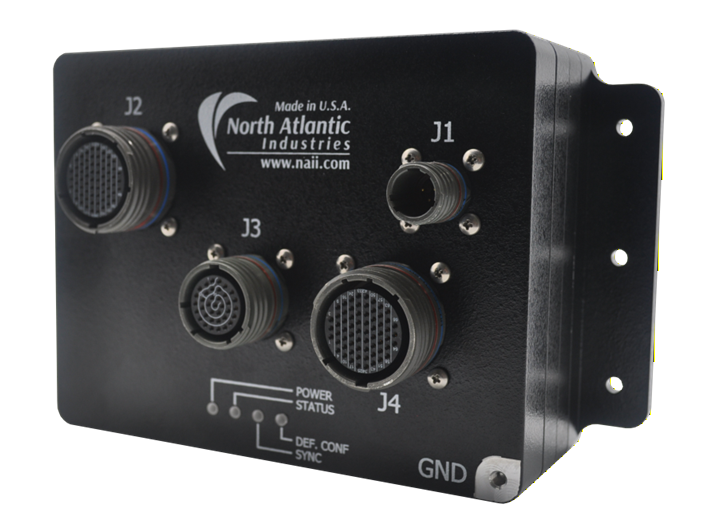
Figure 1. NIU2A-TT2
Unpacking
The NIU2A-TT2 packing materials were designed specifically for transport protection of the NIU2A-TT2. When receiving the shipment container, inspect packaging for any evidence of physical damage. If damage is evident, it is recommended that the carrier agent is present when opening the shipping container. It is further recommended that all packing material is retained in the event the NIU2A-TT2 needs to be shipped elsewhere.
System/Chassis Identification
An identification label, indicating part number, unique serial number and Ethernet PHY MACs / default IP address(es) is affixed to the system chassis.
IMAGE PENDING

Figure 2. Unit Identification
Inspection
Inspect the chassis and connectors to ensure that they were not damaged during transit.
MECHANICAL INTERFACE
Mechanical Description
The NIU2A-TT2 is a rugged, aluminum, conduction-cooled system. It must be mounted to a cold plate. The system thermal management design considerations should ensure that the chassis thermal interface (NIU2A bottom surface) does not exceed 71°C. Mounting holes are provided on the chassis bottom housing flanges (as depicted). See the outline drawing below.
Mounting Requirements
Refer to NIU2A-TT2 Outline and Installation Drawing (OID) or NIU2A-TT2 with Fiber Outline and Installation Drawing (OID) for details on mounting and installing the NIU2A-TT2. It is available for download from NAI’s website. The NIU2A-TT2 is conduction cooled and must be mounted in accordance with the drawing. The OID provides recommended hardware, torque, cold-plate flatness and surface finish specifications, and thermal conductivity requirements.
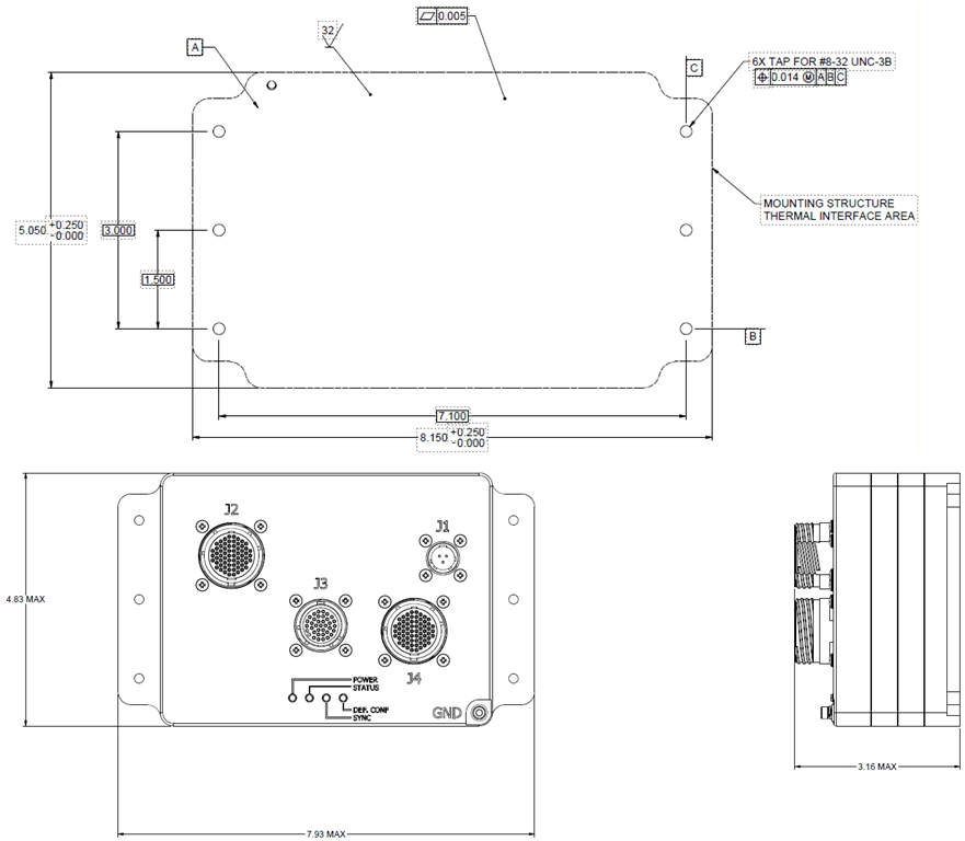
Figure 3. NIU2A-TT2 Outline Dimensions/Cold Plate Mounting Pattern (Reference Only)
Notes:
- For reference only (refer to the product web page for the latest revision NIU2A-TT2 Outline and Installation Drawing (OID).
- Unless otherwise specified, dimensions are in inches (mm); tolerances are:
- 2 PL DEC ±0.01; 3 PL DEC ±0.005
- FRACT ±1/64 (0.4); ANGLES ±1/2 (12.7)
Chassis (Earth) GND
Chassis ground point threaded insert location is on the connector side of the NIU2A-TT2 as shown.
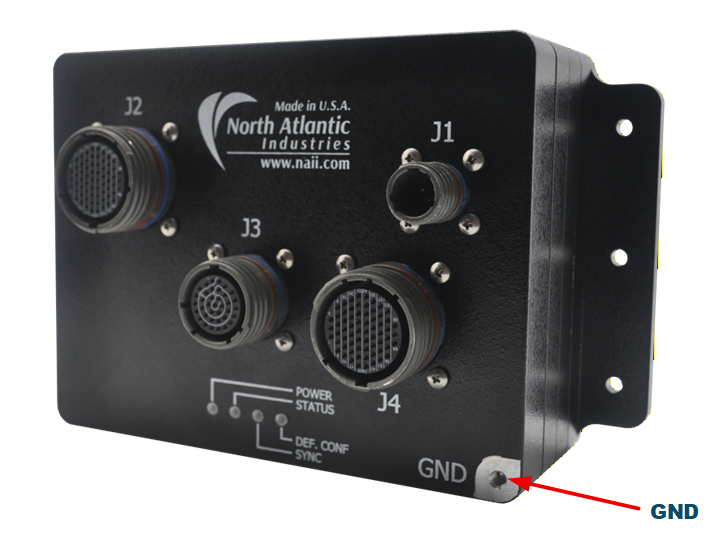
Figure 4. NIU2A-TT2 Outline Dimensions/Chassis GND location
Note
Chassis GND braid or equivalent to be secured by #6-32 screw/studs (with a depth of 0.3 inches) as end application requires. The NIU2A-TT2 chassis is provided with #6-32 threaded insert only. The recommended torque for the NIU2A-TT2 Chassis GND screw is 11 in-lbs. (125 N·cm)
CONNECTOR DESIGNATIONS, LOCATIONS & DESCRIPTIONS
The Power, Ethernet and Maintenance connectors are located on the NIU2A-TT2 front panel housing.
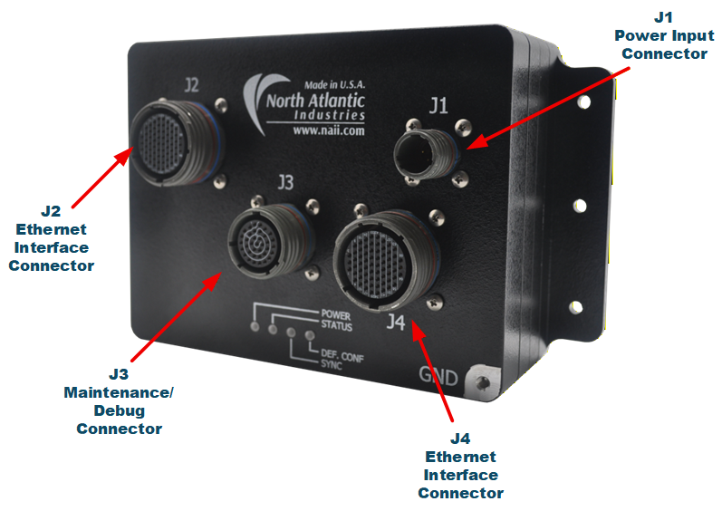
Figure 5. NIU2A-TT2 (Front Panel Connector Placement)
NIU2A-TT2 Connector Designation and Description
| Connector Designation | Description |
| J1 | Primary Power Connector, 28 VDC (nominal) |
| J2 | 66-Pin Ethernet Connector: 100BASE-T Switch Ports 7-12, 21-24; 1GBASE-T Switch Ports 5, 6; 1GBASE-T Mirror Port 25 |
| J3 | 37-Pin Maintenance Connector: TTE Configuration Select, RS-232, I2C, Discretes (Maintenance/Ground/Shop Mode, Reset, Write Protect, Power Down, Watchdog Disable) |
| J4 | 66-Pin Ethernet Connector: 100BASE-T Switch Ports 13-20; 1GBASE-T Switch Ports 1-4 |
Connector Details and Pinout
Generic pinout. See module I/O section or contact factory regarding any special module I/O configuration.
J1, Primary Power Connector
Primary input power is supported on the NIU2A-TT2 via the J1 connector. Power input for the NIU2A-TT2: 28 VDC (nominal, standard, default).
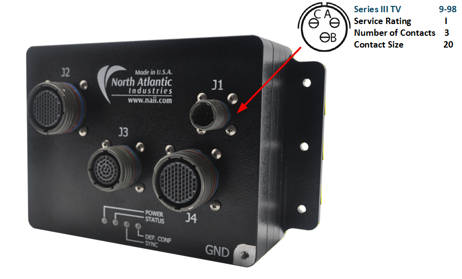
Figure 6. J1 Primary Power Connector Detail
Parts Identification
J1 Primary Power Connector Definition
| Chassis (Box-level) | Mating Cable Connector | ||||
| Designation | MIL-DTL Equivalent Reference | Shell/Insert | Pin-count | MIL-DTL Equivalent Reference | NAI P/N (for reference) |
| J1 | D38999/20WA98PA (10,000 pF, incl. ‘c-filter') | 9 / 98 | 3 | D38999/26WA98SA | 05-0297-COM |
Pinout
J1 Primary Power Connector Pinout
| J1 Connector Pin | Signal |
| A | Chassis GND |
| B | 28VDC-RTN |
| C | 28VDC |
J2, Ethernet Switch Ports (7-12, 21-24, 5, 6 & Mirror 25)
The NIU2A-TT2 J2 66-pin Ethernet connector supports ten 100BASE-T TTE Switch ports (Ports 7 through 12 and Ports 21 through 24), two 1GBASE-T TTE Switch ports (Ports 5 and 6), and the 1GBASE-T Mirror/Monitor port (Port 25).
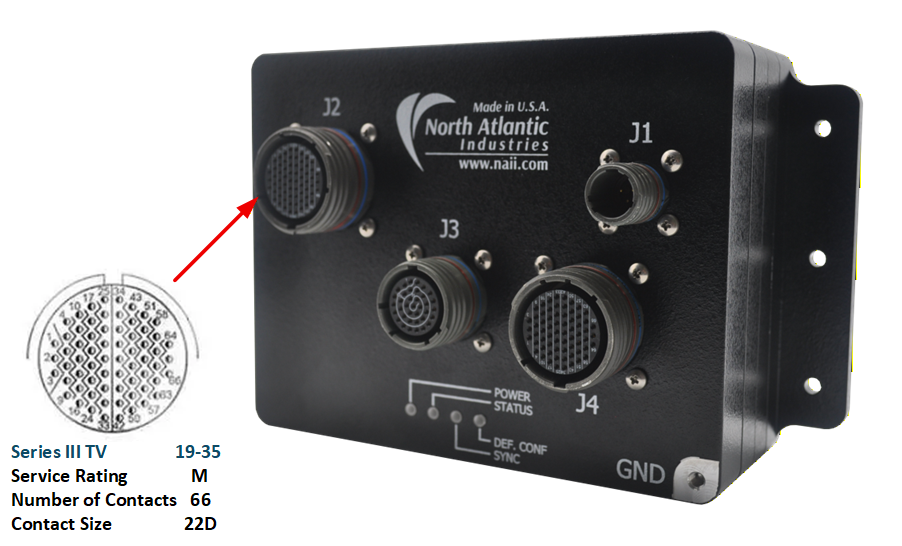
Figure 7. J2 Ethernet Switch Ports (7-12, 21-24, 5, 6 & Mirror 25)
Parts Identification
J2 Ethernet Connector Definition
| Chassis (Box-level) | Mating Cable Connector | ||||
| Designation | MIL-DTL Equivalent Reference | Shell/Insert | Pin-count | MIL-DTL Equivalent Reference | NAI P/N (for reference) |
| J2 | D38999/20WF35SN | 19 / 35 | 66 | D38999/26WF35PN | 05-0284-COM |
Pinout
J2 Ethernet Connector Pinout
| J2 Connector Pin | Signal | Notes |
| 45 | ETH5_TP0N | *1 |
| 46 | ETH5_TP0P | *1 |
| 43 | ETH5_TP1N | *1 |
| 44 | ETH5_TP1P | *1 |
| 52 | ETH5_TP2N | *1 |
| 53 | ETH5_TP2P | *1 |
| 58 | ETH5_TP3N | *1 |
| 51 | ETH5_TP3P | *1 |
| 66 | ETH6_TP0N | *1 |
| 65 | ETH6_TP0P | *1 |
| 62 | ETH6_TP1N | *1 |
| 63 | ETH6_TP1P | *1 |
| 59 | ETH6_TP2N | *1 |
| 64 | ETH6_TP2P | *1 |
| 60 | ETH6_TP3N | *1 |
| 61 | ETH6_TP3P | *1 |
| 56 | ETH7_TP0N | *1 |
| 57 | ETH7_TP0P | *1 |
| 49 | ETH7_TP1N | *1 |
| 50 | ETH7_TP1P | *1 |
| 41 | ETH8_TP0N | *1 |
| 42 | ETH8_TP0P | *1 |
| 32 | ETH8_TP1N | *1 |
| 33 | ETH8_TP1P | *1 |
| 15 | ETH9_TP0N | *1 |
| 16 | ETH9_TP0P | *1 |
| 8 | ETH9_TP1N | *1 |
| 9 | ETH9_TP1P | *1 |
| 7 | ETH10_TP0N | *1 |
| 3 | ETH10_TP0P | *1 |
| 1 | ETH10_TP1N | *1 |
| 2 | ETH10_TP1P | *1 |
| 4 | ETH11_TP0N | *1 |
| 5 | ETH11_TP0P | *1 |
| 10 | ETH11_TP1N | *1 |
| 11 | ETH11_TP1P | *1 |
| 27 | ETH12_TP0N | *1 |
| 28 | ETH12_TP0P | *1 |
| 25 | ETH12_TP1N | *1 |
| 26 | ETH12_TP1P | *1 |
| 23 | ETH21_TP0N | *1 |
| 24 | ETH21_TP0P | *1 |
| 21 | ETH21_TP1N | *1 |
| 22 | ETH21_TP1P | *1 |
| 13 | ETH22_TP0N | *1 |
| 14 | ETH22_TP0P | *1 |
| 6 | ETH22_TP1N | *1 |
| 12 | ETH22_TP1P | *1 |
| 19 | ETH23_TP0N | *1 |
| 20 | ETH23_TP0P | *1 |
| 17 | ETH23_TP1N | *1 |
| 18 | ETH23_TP1P | *1 |
| 36 | ETH24_TP0N | *1 |
| 37 | ETH24_TP0P | *1 |
| 34 | ETH24_TP1N | *1 |
| 35 | ETH24_TP1P | *1 |
| 54 | ETH25_TP0N | *1 |
| 55 | ETH25_TP0P | *1 |
| 47 | ETH25_TP1N | *1 |
| 48 | ETH25_TP1P | *1 |
| 39 | ETH25_TP2N | *1 |
| 40 | ETH25_TP2P | *1 |
| 30 | ETH25_TP3N | *1 |
| 31 | ETH25_TP3P | *1 |
| 29 | GND | Signal/System Ground |
| 38 | GND | Signal/System Ground |
Notes
*1: TTE Switch Ethernet signal definitions:
      ETHnn_TPx(y) where:
      nn = Ethernet Switch Port number
      x = Twisted pair/differential signal number (0, 1, 2, or 3)
      y = Differential signal polarity (P=positive(+) and N=negative(-))
10/100BASE-T ports use two twisted pairs (TP0, TP1). 10/100/1000BASE-T ports use four twisted pairs (TP0 through TP3).
J3, Maintenance, Configuration & Debug
The NIU2A-TT2 J3 37-pin Maintenance connector provides the TT2 TTE Switch module maintenance, configuration and debug signals: TTE Configuration Select [0..5], RS-232 management & debug port (TX, RX, SYSGND), I2C (SCL/SDA), and discrete controls (Power Down, Write Protect, External Reset, Watchdog Disable, Maintenance Mode, Ground Mode, Shop Mode).
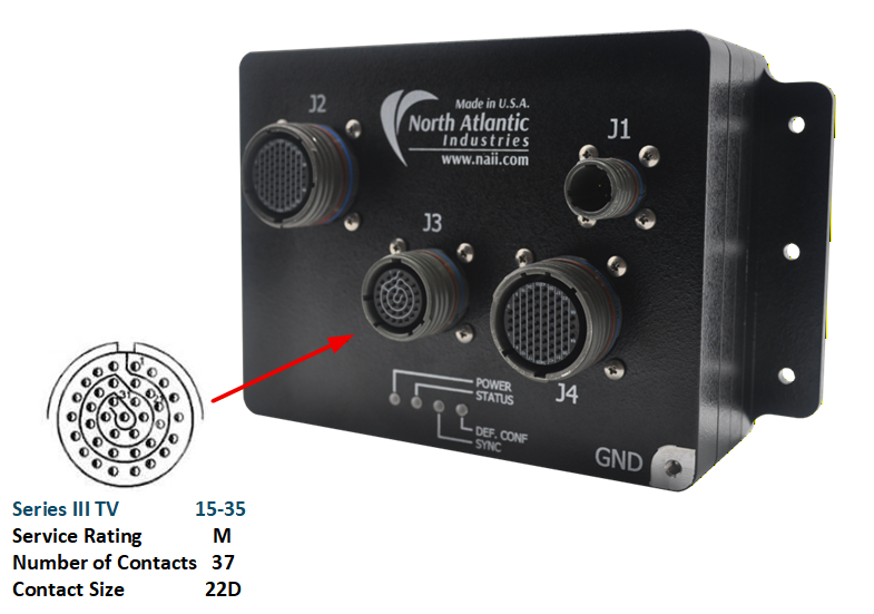
Figure 8. J3 Maintenance, Configuration & Debug Connector Detail
Parts Identification
J3 Maintenance, Configuration & Debug Connector Definition
| Chassis (Box-level) | Mating Cable Connector | ||||
| Designation | MIL-DTL Equivalent Reference | Shell/Insert | Pin-count | MIL-DTL Equivalent Reference | NAI P/N (for reference) |
| J3 | D38999/20WD35SN | 15 / 35 | 37 | D38999/26WD35PN | 05-0302-COM |
Pinout
J3 Maintenance, Configuration & Debug Connector Pinout
| J3 Connector Pin | Signal | Notes |
| 1 | TTE-CONF_SEL_4 | TTE Configuration Select bit 4 (pull-up on module) |
| 2 | TTE-CONF_SEL_0 | TTE Configuration Select bit 0 (pull-up on module) |
| 3 | TTE-CONF_SEL_1 | TTE Configuration Select bit 1 (pull-up on module) |
| 5 | TTE-CONF_SEL_2 | TTE Configuration Select bit 2 (pull-up on module) |
| 7 | WRITE_PROTECTn | Write Protect, active low (pull-up on module) |
| 9 | TTE-CONF_SEL_3 | TTE Configuration Select bit 3 (pull-up on module) |
| 11 | SPARE3 | Spare |
| 13 | MAINT_MODE | Maintenance Mode discrete (pull-down on module) |
| 15 | 3.3_A | 3.3 V (A) |
| 16 | SYSGND (RS-232) | RS-232 Serial Ground |
| 17 | EXT_RS232_RX | RS-232 Receive (maintenance/debug) |
| 18 | EXT_RS232_TX | RS-232 Transmit (maintenance/debug) |
| 21 | TTE-CONF_SEL_5 | TTE Configuration Select bit 5 (pull-up on module) |
| 23 | PWR-DWNn | Power Down, active low (pull-up on module) |
| 25 | SYSGND | Signal/System Ground |
| 26 | GROUND_MODE | Ground Mode discrete (pull-down on module) |
| 27 | SHOP_MODE | Shop Mode discrete (pull-down on module) |
| 28 | EXT_RESET_INn | External Reset input, active low (pull-up on module) |
| 29 | WD_DISABLE | Watchdog Disable discrete |
| 30 | SYSGND | Signal/System Ground |
| 31 | SYSGND | Signal/System Ground |
| 32 | SYSGND | Signal/System Ground |
| 33 | SYSGND | Signal/System Ground |
| 34 | I2C_SCL | I2C Clock (pull-up on module) |
| 35 | I2C_SDA | I2C Data (pull-up on module) |
| 36 | SPARE4 | Spare |
| 37 | SYSGND | Signal/System Ground |
Note
DRAFT: J3 pins not listed above are No-Connect (verify against the released NIU2A-TT2 Interface Control Document prior to release). Discrete polarity, pull-up/pull-down provisions and electrical levels are to be confirmed. For definitions and use of the TTE Configuration Select and maintenance discretes with respect to the SMC2 Switch Module Core, contact TTTech (or the NAI factory).
J4, Ethernet Switch Ports (13-20 & 1-4)
The NIU2A-TT2 J4 66-pin Ethernet connector supports eight 100BASE-T TTE Switch ports (Ports 13 through 20) and four 1GBASE-T TTE Switch ports (Ports 1 through 4).
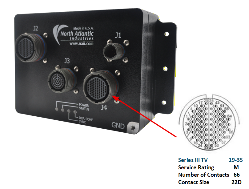
Figure 9. J4 Ethernet Connector Detail
Parts Identification
J4 Ethernet Connector Definition
| Chassis (Box-level) | Mating Cable Connector | ||||
| Designation | MIL-DTL Equivalent Reference | Shell/Insert | Pin-count | MIL-DTL Equivalent Reference | NAI P/N (for reference) |
| J4 | D38999/20WF35SA | 19 / 35 | 66 | D38999/26WF35PA | 05-0285-COM |
Pinout
J4 Ethernet Connector Pinout
| J4 Connector Pin | Signal | Notes |
| 53 | ETH1_TP0N | *1 |
| 45 | ETH1_TP0P | *1 |
| 37 | ETH1_TP1N | *1 |
| 28 | ETH1_TP1P | *1 |
| 58 | ETH1_TP2N | *1 |
| 51 | ETH1_TP2P | *1 |
| 59 | ETH1_TP3N | *1 |
| 52 | ETH1_TP3P | *1 |
| 54 | ETH2_TP0N | *1 |
| 46 | ETH2_TP0P | *1 |
| 47 | ETH2_TP1N | *1 |
| 38 | ETH2_TP1P | *1 |
| 65 | ETH2_TP2N | *1 |
| 64 | ETH2_TP2P | *1 |
| 61 | ETH2_TP3N | *1 |
| 60 | ETH2_TP3P | *1 |
| 56 | ETH3_TP0N | *1 |
| 55 | ETH3_TP0P | *1 |
| 48 | ETH3_TP1N | *1 |
| 39 | ETH3_TP1P | *1 |
| 66 | ETH3_TP2N | *1 |
| 62 | ETH3_TP2P | *1 |
| 57 | ETH3_TP3N | *1 |
| 63 | ETH3_TP3P | *1 |
| 31 | ETH4_TP0N | *1 |
| 40 | ETH4_TP0P | *1 |
| 33 | ETH4_TP1N | *1 |
| 32 | ETH4_TP1P | *1 |
| 50 | ETH4_TP2N | *1 |
| 49 | ETH4_TP2P | *1 |
| 42 | ETH4_TP3N | *1 |
| 41 | ETH4_TP3P | *1 |
| 14 | ETH13_TP0N | *1 |
| 13 | ETH13_TP0P | *1 |
| 16 | ETH13_TP1N | *1 |
| 15 | ETH13_TP1P | *1 |
| 8 | ETH14_TP0N | *1 |
| 9 | ETH14_TP0P | *1 |
| 6 | ETH14_TP1N | *1 |
| 7 | ETH14_TP1P | *1 |
| 10 | ETH15_TP0N | *1 |
| 4 | ETH15_TP0P | *1 |
| 17 | ETH15_TP1N | *1 |
| 18 | ETH15_TP1P | *1 |
| 25 | ETH16_TP0N | *1 |
| 26 | ETH16_TP0P | *1 |
| 34 | ETH16_TP1N | *1 |
| 35 | ETH16_TP1P | *1 |
| 22 | ETH17_TP0N | *1 |
| 24 | ETH17_TP0N | *1 |
| 21 | ETH17_TP0P | *1 |
| 23 | ETH17_TP0P | *1 |
| 2 | ETH18_TP0N | *1 |
| 3 | ETH18_TP0P | *1 |
| 5 | ETH18_TP1N | *1 |
| 1 | ETH18_TP1P | *1 |
| 11 | ETH19_TP0N | *1 |
| 12 | ETH19_TP0P | *1 |
| 19 | ETH19_TP1N | *1 |
| 20 | ETH19_TP1P | *1 |
| 36 | ETH20_TP0N | *1 |
| 27 | ETH20_TP0P | *1 |
| 43 | ETH20_TP1N | *1 |
| 44 | ETH20_TP1P | *1 |
| 29 | GND | Signal/System Ground |
| 30 | GND | Signal/System Ground |
Notes
*1: TTE Switch Ethernet signal definitions:
      ETHnn_TPx(y) where:
      nn = Ethernet Switch Port number
      x = Twisted pair/differential signal number (0, 1, 2, or 3)
      y = Differential signal polarity (P=positive(+) and N=negative(-))
10/100BASE-T ports use two twisted pairs (TP0, TP1). 10/100/1000BASE-T ports use four twisted pairs (TP0 through TP3).
POWER-UP & OPERATIONAL DESCRIPTION
Panel LEDs & Functions
Front Panel LEDs indications.
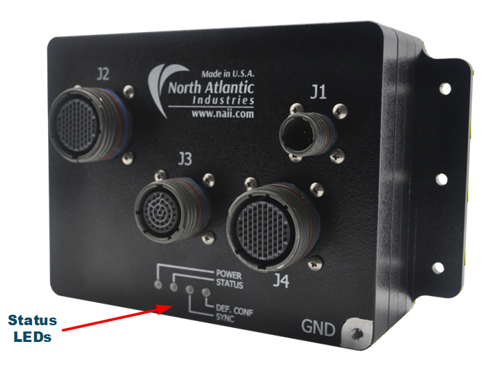
Figure 10. NIU2A-TT2 Status LEDs Location
NIU2A-TT2 Status LEDs Function
| LED | STATUS / FUNCTION | |
| ILLUMINATED | EXTINGUISHED | |
| POWER (GRN): | Power-On (TBD) | Power-off |
| STATUS (RED/GRN): | TT2 Switch Module status indication, bi-color (TBD - contact TTTech/factory) | |
| SYNC: | TTE synchronization status indication (TBD - contact TTTech/factory) | |
| DEF CONF: | Default Configuration indication (TBD - contact TTTech/factory) | |
Note
DRAFT: Conferring with Engineering on full descriptions of LEDs.
ETHERNET WIRING CONVENTION
| RJ-45 Pin | T568A Color | T568B Color | 10/100Base-T | 1000BASE-T | NAI wiring convention |
| 1 | white/green stripe | white/orange stripe | TX+ | DA+ | ETH-TP0+ |
| 2 | green | orange | TX+ | DA- | ETH-TP0- |
| 3 | white/orange stripe | white/green stripe | RX+ | DB+ | ETH-TP1+ |
| 4 | blue | blue | DC+ | ETH-TP2+ | |
| 5 | white/blue stripe | white/blue stripe | DC- | ETH-TP2- | |
| 6 | orange | green | RX- | DB- | ETH-TP1- |
| 7 | white/brown stripe | white/brown stripe | DD+ | ETH-TP3+ | |
| 8 | brown | brown | DD- | ETH-TP3- |
TT2 TTE SWITCH MODULE - OVERVIEW
The NIU2A-TT2 is pre-configured with the TT2 Time-Triggered Ethernet (TTE) Switch Module, which is based on TTTech’s certifiable TTEthernet® SMC2 Ethernet Switch Module Core (Certifiable Flight Hardware). The following high-level information is based on the NIU2A-TT2 data sheet.
Ethernet Switching Capability
- 18x 10/100BASE-T ports
- 6x 10/100/1000BASE-T ports
- 1x 10/100/1000BASE-T Mirror port
Switch Processor Configurable Traffic Classes
The TT2 supports concurrent operation of three traffic classes:
- Best-effort traffic (IEEE 802.3)
- Rate-constrained traffic (full ARINC 664 Part 7 / AFDX®)
- Time-triggered traffic (SAE AS6802 Standard)
By supporting all three traffic classes, the NIU2A-TT2 configuration allows users of IEEE 802.3 Ethernet to upgrade to Deterministic Ethernet (ARINC 664 Part 7 AFDX® or Time-Triggered Ethernet SAE AS6802) protocols in the future without requiring hardware changes.
End System Interoperability
The NIU2A-TT2 seamlessly communicates with the NAI TE2, a single-port, tri-redundant, deterministic Ethernet communications End System module built on TTTech’s certifiable TTEthernet® IP core, enabling access to NAI’s COSA® family of products.
Configuration & Maintenance
Switch configuration selection and maintenance functions are supported via the J3 Maintenance connector, including the TTE Configuration Select discretes (TTE-CONF_SEL [0..5]), RS-232 management & debug port, I2C, and mode/control discretes (Maintenance Mode, Ground Mode, Shop Mode, Power Down, Write Protect, External Reset, Watchdog Disable). Refer to the J3 connector section of this manual for signal details.
Certifiable Artifacts Package
- To DAL A: DO-254, DO-178C (Pending - contact factory)
Note
This section intentionally provides only high-level information about the TT2 TTE Switch Module. Detailed information regarding the TTEthernet® SMC2 Switch Module Core - including switch configuration and loading, network design and scheduling, traffic class provisioning, synchronization, toolchain, and certification artifacts - is provided by TTTech. For more information, users should contact TTTech.
NIU2A-TT2 PART NUMBER DESIGNATION
For a complete breakdown of product configuration and option details, click here for the NIU2A-TT2 part number designation.
REVISION HISTORY
| Revision Date | Description |
|---|---|
| 2026-07-13 | Preliminary draft of NIU2A-TT2 manual. |
NAI Cares
North Atlantic Industries (NAI) is a leading independent supplier of Embedded I/O Boards, Single Board Computers, Rugged Power Supplies, Embedded Systems and Motion Simulation and Measurement Instruments for the Military, Aerospace and Industrial Industries. We accelerate our clients’ time-to-mission with a unique approach based on a Configurable Open Systems Architecture™ (COSA®) that delivers the best of both worlds: custom solutions from standard COTS components.
We have built a reputation by listening to our customers, understanding their needs, and designing, testing and delivering board and system-level products for their most demanding air, land and sea requirements. If you have any applications or questions regarding the use of our products, please contact us for an expedient solution.
Please visit us at: www.naii.com or select one of the following for immediate assistance:
Documentation
FAQ
Application Notes
http://www.naii.com/applicationnotes
Calibration and Repairs
http://www.naii.com/calibrationrepairs
Call Us
(631) 567-1100
Link to original