
The NAI VPX series of power supplies supports remote error sensing on the main regulated outputs, and on some optional configurations it is also available on the +3.3V_Aux output. Remote sense can compensate for up to 0.5 V of voltage drop on each of these outputs. The power supply regulates based on where the sense is tied.
Most systems contain a single board computer or similar card. These cards tend to have watchdog circuits that monitor the power rails. If the card senses the power rails going out of tolerance, it may send a System Reset command to the rest of the system. It is best to terminate the remote sense lines close to where any watchdogs of this nature are located. If there is no such watchdog, the next choice is about half of the path to the heaviest load.
Sense wiring implementation
- Connect each S+ pin to the positive voltage rail pad where the load is connected (the point of regulation, not the supply’s output pin).
- Connect each S– pin to the return/ground at the load (close to the load and not at the supply).
Sense wiring to the load, or point of regulation (POR), tells the power supply to measure the voltage right at the load’s pins rather than at its own pins, so it can regulate out any drop between itself and the load.
In the backplane it is best to keep the sense lines tightly coupled via adjacent PCB traces to minimize noise pickup. If the POR is on another VPX card, ensure the backplane routing takes the sense leads directly to that card’s power pads, not through high-current copper before them.
In cases where remote sense is not needed or the sense wires may open, ensure the sense lines are terminated to the local sense terminals (or main output) so the supply reverts to local regulation.
Below is a simplified diagram showing the implementation of remote sense on VS1 through VS3.
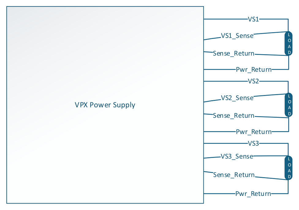
Remote sense wiring on VS1 through VS3. Each output’s VSx_Sense and Sense_Return are connected at the load (the point of regulation), alongside the output rail and Pwr_Return.