
Introduction
MIL-STD-461 is the Department of Defense standard for the electromagnetic interference (EMI) characteristics of equipment. It covers both sides of EMI: emissions (the noise a unit puts out) and susceptibility (the noise a unit must tolerate without misbehaving). The current revision is H (April 2026). This note references MIL-STD-461G, published in 2015, which is currently the contractual basis for most active programs.
A switching power supply is often one of the more significant EMI contributors in a system, since its switching activity produces noise on the power leads, so the supply deserves early attention. Power supplies and other electronic assemblies can generally be divided into two major categories: Embedded and Stand-Alone. An Embedded product is intended to be installed within a larger system. The system enclosure can contribute to environmental protection and EMI shielding, and the system can include additional filtering to improve EMI performance. The output power from an Embedded power supply is typically distributed only to components within the system. A Stand-Alone power supply functions as a system-level equipment item. It should meet the applicable environmental and EMI requirements without relying on a separate enclosure or filtering to provide the required protection or shielding.
This is an important distinction because the test standards are generally written to qualify system-level equipment, not individual Embedded components. Although an Embedded-product manufacturer may not be contractually responsible for compliance of the completed system, a responsible supplier should characterize the product’s performance using fixtures that simulate the intended system-level configuration. The supplier should also clearly define the product’s installation requirements, intended use, and the configuration and conditions under which it was qualified. Signals for communication, monitoring, and control that are normally internal to a system should be routed through a shielded interface so that testing is representative of the intended installation.
This approach does not guarantee compliance of the completed system, but it provides a strong path toward successful integration and qualification. EMI compliance is ultimately a system-level outcome that depends both on the power supply and on how the surrounding system is grounded, shielded, and wired. This note outlines practical guidelines at each level.
The tests most relevant to power
MIL-STD-461 defines a family of tests. A handful bear most directly on power.
- Conducted emissions on the power leads: CE101 at lower frequencies (applicable primarily to Navy and Army aircraft platforms) and CE102 in the RF range. This is where switching-frequency noise tends to appear, and CE102 is one of the most commonly applied tests.
- Conducted susceptibility: CS101 on the power leads, along with the bulk-cable-injection and transient tests (CS114, CS115, CS116) and lightning indirect effects (CS117, commonly required on airborne platforms). These check that the equipment keeps working through noise coupled onto its cables.
- Radiated emissions: RE101 for magnetic fields and RE102 for electric fields. These cover what the unit and its cabling radiate.
- Radiated susceptibility: RS101 for magnetic fields and RS103 for electric fields. These evaluate the ability to operate in externally generated fields.
Which tests apply, and at what limits, depends on the platform, so always work from the requirements called out for your program.
CE102 conducted-emissions test setup
In practice, CE102 emissions on the power leads are measured with the arrangement shown below. The unit under test is mounted and bonded to a conductive ground plane, with a LISN on each power lead presenting a controlled impedance and providing the measurement port for the EMI receiver.
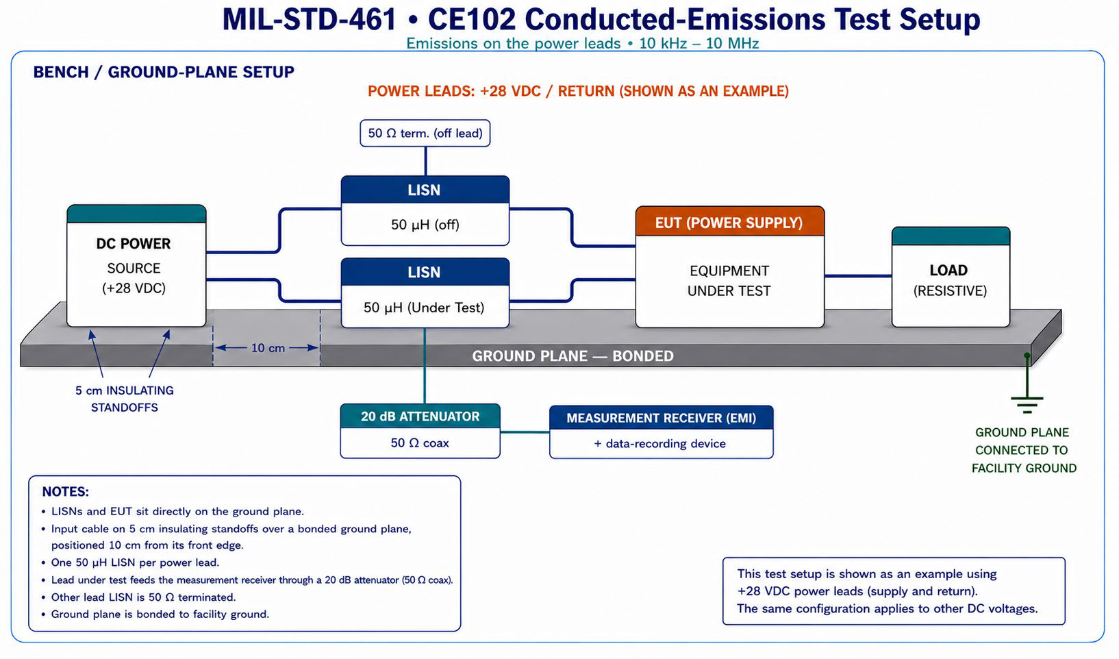
Representative CE102 setup: input cable on 5 cm insulating standoffs over a bonded ground plane, positioned 10 cm from its front edge; one 50 µH LISN per power lead, with the lead under test feeding the measurement receiver through a 20 dB attenuator while the other LISN is 50 Ω terminated. Cables for loads and other signals should represent the intended application. Applicable tests and limits depend on the program.
Where compliance is won
It helps to separate what the power supply contributes from what the surrounding system contributes. A clean supply gives you a head start, but the installation determines whether that advantage survives to the platform. The two levels are summarized below.
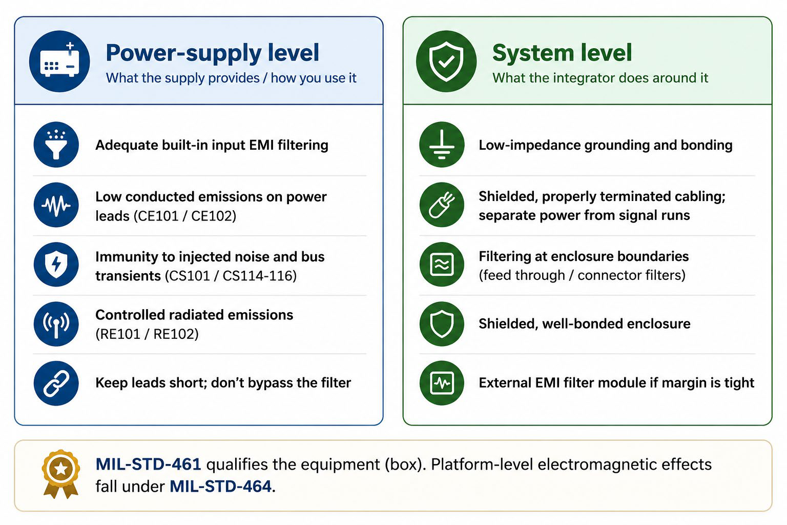
Where EMI compliance is won: what the power supply provides versus what the system integrator does around it. MIL-STD-461 qualifies the equipment; platform-level electromagnetic effects fall under MIL-STD-464.
At the power supply level
Start with filtering margin — Choose a supply with adequate built-in input EMI filtering. A supply that already sits comfortably below the conducted-emissions limit gives you margin to work with before you add anything externally, rather than forcing the system design to make up a deficit.
Know where switching noise shows up — Conducted-emissions failures are frequently traced to switching-frequency components and their harmonics on the power leads (the CE102 range). Conducted emissions generally consist of both differential-mode and common-mode components, each requiring different filtering techniques; effective EMI filter design addresses both mechanisms. When selecting a supply, favor one whose emissions profile has real headroom to the applicable limit at your operating voltage. Passing CE102 with only 1–2 dB of margin in a laboratory configuration may not provide sufficient robustness once installation effects are introduced.
Confirm the supply’s own immunity — Emissions are only half of EMI. Confirm the supply rides through the conducted-susceptibility conditions (noise and transients injected on its leads) without functional degradation, dropout, or loss of regulation, so it does not become the weak point during susceptibility testing.
Do not defeat the supply’s design — Keep input and output leads short, use any external capacitors the datasheet calls for, and do not bypass or undersize the supply’s filtering. Good box-level EMI behavior is easy to undo with careless wiring at installation.
At the system level
Ground and bond well — A low-impedance bonding path and solid bonding between the supply, the enclosure, and the chassis is the foundation of EMI control. Poor bonding will undermine an otherwise clean design and is a common root cause of both emissions and susceptibility failures.
Shield and route cables deliberately — Cable construction and routing should represent the intended application. Input power cables are typically unshielded. Cables for load, communication, monitoring and control may be shielded if that is the intended application or if these cables do not exit the intended system chassis. When shields are used they should be properly terminated (360° terminations where practical); keep runs as short as practical, and separate noisy power cabling from sensitive signal cabling. Cables are efficient antennas, so cable discipline is often what makes or breaks radiated-emissions results. Once power supply conducted emissions are adequately controlled, cable routing and enclosure design frequently become the dominant factors determining RE102 performance.
Filter at the boundaries — Add filtering or feed-through/connector filters where leads cross the enclosure boundary. Containing conducted noise at the point it would otherwise leave the box is far more effective than trying to suppress it after it has spread.
Shield the enclosure — A properly shielded, well-bonded enclosure controls both radiated emissions and radiated susceptibility. Gaps, unshielded openings, and poor seams can reduce shielding effectiveness.
Add external filtering if margin is tight — If box-level margin is marginal for the platform limits, a properly selected external EMI filter at the input is a proven way to close the gap without redesigning the supply.
461 versus 464
It is worth keeping the scope straight. MIL-STD-461 establishes emission and susceptibility requirements for individual equipment and subsystems. The overall platform electromagnetic environment, including how multiple pieces of equipment coexist, falls under MIL-STD-464 at the system level. Designing equipment to its 461 limits is necessary, but the platform integrator carries system-level EMC obligations as well.
The takeaway
Successful EMI compliance is achieved through both equipment design and system integration. A supply chosen for filtering margin and good immunity, combined with disciplined grounding, shielding, cabling, and boundary filtering at the system level, is the reliable path through MIL-STD-461. Addressing both levels early, rather than discovering a shortfall at the test lab, is what keeps an EMI qualification on schedule.
See also
- MIL-STD-461 — overview of the standard and its CE/CS/RE/RS test families