
Overview
NAI’s 56TS1 is a high power density, low profile, AC/DC switch mode power supply in a 500 Watt single output configuration. The 56TS1 accepts a three-phase AC input and a +270 VDC input. This COTS unit provides a single full-power output (500 Watts) at a baseplate temperature of +85°C.
Current share description
Current share is a standard feature provided to allow multiple units to act in parallel for additional power capability or N+1 redundancy. NAI utilizes a proprietary algorithm to provide sharing. The algorithm uses bi-directional communication through the pins designated as “share” on the interface connector. The units will negotiate to determine a master; the remaining units will act as slaves. The master will vary the output voltage of the slaves to achieve sharing.
The signal on the share pins uses a linear level proportional to the load current. The power supply provides filtering and buffering of these signals.
Effect on output ripple
The power supplies use high frequency switching techniques to provide isolated and regulated power. The power supplies rectify and filter the high frequency power. As a result, the output rails of the power supplies contain residual high frequency ripple. The switching circuits within each supply are synchronized, however there is no synchronization between individual power supplies. The resulting ripple on the output rails will contain a low frequency beat. The amplitude of the ripple will increase but not above the specification limit of an individual power supply.
Load balancing limits
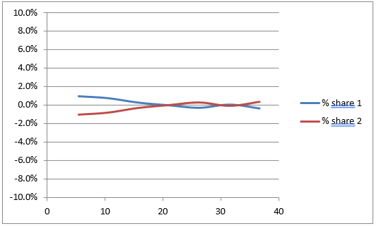
The share performance will be within 5% of the rated load, calculated as follows:

In text form: (IPS1 − Itotal applied load / n) / (rated load for each unit) < 5% × (n − 1), where n is the number of paralleled units.
For example, for a dual shared configuration, the error for a 20 amp rated power supply output will be ±1 amp from the ideal value of one half of the total load.
BIT performance
Each unit will have its own BIT information available through the discrete output Share_OK*. Each unit will provide its own report. An active low (conducting current) will indicate a functioning unit. This is intended as an indicator driver.
Connections
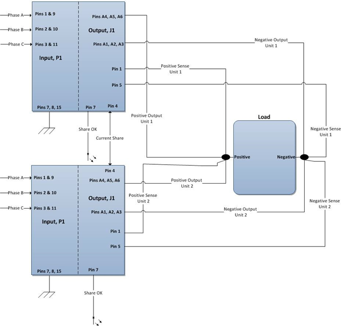
Best practices should be employed to minimize noise on the share pins and sense lines. To achieve sharing, all share and sense lines need to be connected. The sense lines from multiple power supplies should be terminated to the same single point. Refer to the example connection diagram below.
56TS1 Power Supply Current Share Diagram
Sharing at power-up
The sharing feature will engage once the output reaches its final level. Typical performance for a dual shared configuration is shown below. The current settles after an initial adjustment period, as seen in the pink trace.
Total load is 35.7 Amps on two paralleled power supplies.
| Channel | Scale | Trace |
|---|---|---|
| CH1 | 10 A/div | Load current of one supply |
| CH2 | 5.0 V/div, 15.0 V offset | Load voltage (thick trace) |
Timebase: 0.04 s/div, 0.0 s delay. Scope readout: Module 1 rise time = 0.0528 (turn-on), Vmax = 27.66 Volts.
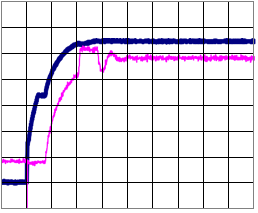
Channel 1 is the load current of one supply. Channel 2 is the load voltage (thick trace).
Sharing performance during load transient
Total load is stepped from 17.85 amps to 35.7 amps. The sharing circuitry tracks changes in load conditions.
| Channel | Scale | Trace |
|---|---|---|
| CH1 | 20 A/div | Load current of one unit |
| CH2 | 1.0 V/div, 0.0 V offset | Output pulse load response (thick trace) |
Timebase: 0.002 s/div. Scope readout: Module 1, 17.85 to 35.7 Amps; dynamic response = 1.031 Vp.
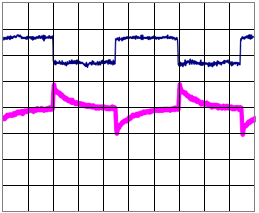
Channel 1 is the load current of one unit. Channel 2 is the output pulse load response (thick trace).
Sharing circuit during a simulated failure
PS1 is commanded off. The output current of PS2 increases to maintain load current.
Total load is set to 17.85 Amps.
| Channel | Scale | Trace |
|---|---|---|
| CH1 | 10 A/div | Operating unit load current |
| CH2 | 5.0 V/div, 15.0 V offset | Load voltage (thick trace) |
Timebase: 0.002 s/div. Scope readout: Module 1 enable turn-off = 27.3 Vp.
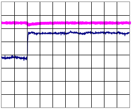
Channel 1 is the operating unit load current. Channel 2 is the load voltage (thick trace).
Sharing performance with a delayed start
This capture simulates multiple input sources or delayed enable commands. Total load is set to 17.85 Amps.
| Channel | Scale | Trace |
|---|---|---|
| CH1 | 5 A/div | Load current of the operating unit |
| CH2 | 5.0 V/div, 15.0 V offset | Load voltage (thick trace) |
Timebase: 0.02 s/div. Scope readout: Module 1 enable turn-on = 27.5131 Vp.

Channel 1 is the load current of the operating unit. Channel 2 is the load voltage (thick trace).
Sharing accuracy
Static load share performance of two units from 3.57 A to 37.5 A load.
See also
- Power conversion terminology help guide — definitions of Current Share, Parallel Operation and Redundancy.
- Power Products FAQ — general current-share implementation guidance.