
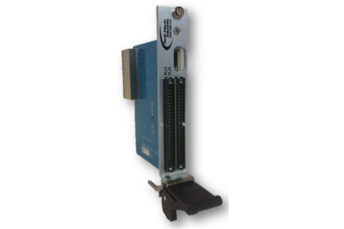
FUNCTION/FEATURES
- High density connectors mimic 75G5 front panel I/O
- cPCI 0.8” pitch rear chassis I/O panel with locking extractor
- Optimized for NAI 75G5 multifunction rear I/O
- Mini-HDMI interface receptacle (utility interface)
DESCRIPTION
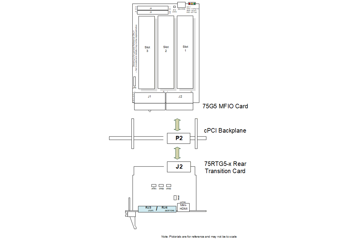
The 75RTG5 3U cPCI Rear I/O Transition Card (RTC) (also referred to as Rear Transition Module or RTM) is for use in cPCI systems/chassis that require reliable interconnection between the rear I/O P2 cPCI connector and the ‘outside world’. The rear I/O P2 connector is terminated in two Harwin 50-pin Datamate connectors and an industry standard mini-HDMI receptacle located on a 0.8” pitch cPCI panel. The panel is provided with an extractor to latch or eject the card from the rear backplane access panel of the cPCI chassis. The 75RTG5 can be used with any 3U cPCI card, but pin-outs are optimized for use with and also mimic, the front panel pin-out of the cPCI NAI Model 75G5 Multifunction I/O (MFIO) card. The mating connector(s) may be mechanically secured using a screwdriver.
SPECIFICATIONS
| Operating Temperature: | 0°C to 70°C |
| Storage Temperature: | -40°C to 85°C |
| Humidity: | 95% RH, non-condensing |
| Protective Covering: | Both sides of the board are protected/covered with solder mask (Conformal coat available on special order – contact factory) |
| I/O Connector Configuration: | Two panel I/O connectors (RJ3, RJ4), Harwin Datamate, male 50-pin type; One mini-HDMI panel jack (Gig-E Port 1 option, serial RS-232 debug) |
| Size: | 3U height, 4HP width (100 mm H x 20.3 mm W x 80 mm D) |
| Weight: | 9 oz. (approx.) |
| RTC I/O Connectors: | Harwin Datamate 50-pin male connectors, 2 mm, Harwin P/N M80-5415022 |
| RTC External I/O Mate Kit: | Two sets I/O mating connector set(s) (includes connector housing, large bore pins and backshell assembly) for the Harwin 50-pin connectors that are supplied with this card (Harwin M80-486 product family mating connector kit Harwin P/N M80-9415005). Additional mating connector kit(s) may be purchased separately under NAI P/N 05-0118 (Contact Factory). |
| Mini-HDMI Panel Receptacle: | Mini-HDMI (19 pos) industry standard type-A receptacle (MHDMR-19-02-H-TH-L-TR, Samtec). |
| Mini-HDMI Mate Kit: | Cable assembly/breakout board adapter kit (not supplied – optional): May be purchased separately under NAI P/N 75SBC4-BB (contact factory). 75SBC4-BB Includes: a. MHDMR-USB-ETH-SER-B003 adapter PWA and b. NAI P/N 07-0030 (Cable Assy. (@ 1 m), (MHDMP to MHDMP) |
75RTG5 INSTALLATION
Figure 1. cPCI MFIO Card + cPCI backplane + 75RTG5 Connection
75RTG5 CONNECTOR/PIN-OUT INFORMATION
Front and Rear Panel Connectors
User I/O is available through the RJ3 & RJ4 RTC panel and mini-HDMI receptacle panel connectors from the 75G5 cPCI J2 user defined rear I/O connector (Figure 2). Refer to 75G5 part number and pin-out information in the Operations Manual.
Caution
Do not connect to any undesignated or (n/c) pins.
Note
The following notes apply unless otherwise specified:
- RTC Front Panel System Ground:
Front panel: RJ3: 1, 26
RJ4: 25, 50
JP10: 13, 19- RTC Front Panel Chassis Ground:
No chassis GND pins available from any dedicated connector pins. When the RTC is secured firmly and the RTC panel plate has electrical continuity between the plate and the securing screws of the system chassis, the jack screw sockets of RJ3, RJ4 and the mini-HDMI receptacle shell will have continuity to the chassis GND.
RTC PANEL CONNECTORS RJ3/RJ4 & JP10
Harwin Datamate 50-pin male connectors, 2 mm, Harwin P/N M80-5415022.
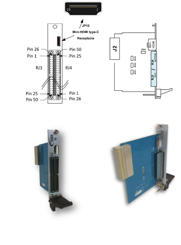
Figure 2. Panel Connectors RJ3, RJ4 and JP10, Placement and Orientation
RTC USER DEFINED I/O PIN-OUTS
Table 1. Rear J2 I/O Definition
| 75RTG5 – Rear J2 I/O; slave I/O | ||||||
| USER I/O | Row | Row | Row | Row | Row | Row |
| J2 | A | B | C | D | E | F |
| 1 | N/C (ETH1-TP1+) | N/C (ETH1-TP1-) | MOD3-DATIO29 / (SER-TXD) | N/C (ETH1-TP3+) | N/C (ETH1-TP3-) | GND |
| 2 | N/C (ETH1-TP0+) | N/C (ETH1-TP0-) | MOD3-DATIO30 / (SER-RXD) | N/C (ETH1-TP2+) | N/C (ETH1-TP2-) | GND |
| 3 | ETH2-TP1+/(MOD2-DATIO27) | ETH2-TP1-/(MOD2-DATIO28) | MOD3-DATIO31 / (SER-GND) | ETH2-TP3+/(MOD2-DATIO31) | ETH2-TP3-/(MOD2-DATIO32) | GND |
| 4 | ETH2-TP0+/(MOD2-DATIO25) | ETH2-TP0-/(MOD2-DATIO26) | MOD3-DATIO12 | ETH2-TP2+/(MOD2-DATIO29) | ETH2-TP2-/(MOD2-DATIO30) | GND |
| 5 | MOD3-DATIO03 | MOD3-DATIO28 / (HDW-WP) | MOD3-DATIO11 | MOD3-DATIO32 / (RTC-STDBY) | N/C | GND |
| 6 | MOD3-DATIO02 | MOD3-DATIO06 | MOD3-DATIO10 | MOD3-DATIO16 | MOD3-DATIO24 | GND |
| 7 | MOD3-DATIO01 | MOD3-DATIO05 | MOD3-DATIO09 | MOD3-DATIO15 | MOD3-DATIO23 | GND |
| 8 | MOD2-DATIO06 | MOD3-DATIO04 | MOD3-DATIO08 | MOD3-DATIO14 | MOD3-DATIO22 | GND |
| 9 | MOD2-DATIO05 | MOD3-DATIO07 | MOD2-DATIO18 | MOD3-DATIO13 | MOD3-DATIO21 | GND |
| 10 | MOD2-DATIO04 | MOD2-DATIO12 | MOD2-DATIO17 | MOD2-DATIO24 | MOD3-DATIO20 | GND |
| 11 | MOD2-DATIO03 | MOD2-DATIO11 | MOD2-DATIO16 | MOD2-DATIO23 | MOD3-DATIO19 | GND |
| 12 | MOD2-DATIO02 | MOD2-DATIO10 | MOD2-DATIO15 | MOD2-DATIO22 | MOD3-DATIO18 | GND |
| 13 | MOD2-DATIO01 | MOD2-DATIO09 | MOD2-DATIO14 | MOD2-DATIO21 | MOD3-DATIO17 | GND |
| 14 | MOD1-DATIO06 | MOD2-DATIO08 | MOD2-DATIO13 | MOD2-DATIO20 | MOD1-DATIO32 | GND |
| 15 | MOD1-DATIO05 | MOD2-DATIO07 | MOD1-DATIO18 | MOD2-DATIO19 | MOD1-DATIO31 | GND |
| 16 | MOD1-DATIO04 | MOD1-DATIO12 | MOD1-DATIO17 | MOD1-DATIO24 | MOD1-DATIO30 | GND |
| 17 | MOD3-DATIO26 / (I2C-SDA) | MOD1-DATIO11 | MOD3-DATIO27 / (cPCI-PRSTn) | MOD1-DATIO23 | MOD1-DATIO29 | GND |
| 18 | MOD3-DATIO25 / (I2C-SCL) | MOD1-DATIO10 | MOD1-DATIO16 | MOD1-DATIO22 | MOD1-DATIO28 | GND |
| 19 | MOD1-DATIO03 | MOD1-DATIO09 | MOD1-DATIO15 | MOD1-DATIO21 | MOD1-DATIO27 | GND |
| 20 | MOD1-DATIO02 | MOD1-DATIO08 | MOD1-DATIO14 | MOD1-DATIO20 | MOD1-DATIO26 | GND |
| 21 | MOD1-DATIO01 | MOD1-DATIO07 | MOD1-DATIO13 | MOD1-DATIO19 | MOD1-DATIO25 | GND |
| 22 | cPCI-GA4 | cPCI-GA3 | cPCI-GA2 | cPCI-GA1 | cPCI-GA0 | GND |
KEY
| = MODULE (1) I/O | = Port 1 / 10/100/1000Base-T | ||
| = MODULE (2) I/O | = Port 2 / 10/100/1000Base-T OR MOD2-DATIO25-32 (option) (definition dependent on 75G5 card configuration option) | ||
| = MODULE (3) I/O | N/C = No connect | ||
| = Motherboard reserved | GND = System (card) Power Ground | ||
| = Maintenance (master) OR MOD3-DATIO25-32 (option) (definition dependent on 75G5 card configuration option) (75RTG5-3 signal references in parenthesis) |
Table 2. Panel RJ3, RJ4 & JP10 Utility I/O Definition
75RTG5 RJ3 (M1, M3) Panel I/O
| BP-J2 | RJ3 PANEL I/O | BP-J2 | |||
| GND | 1 | 26 | GND | ||
| A7 | MOD3-DATIO01 | 2 | 27 | MOD3-DATIO02 | A6 |
| A5 | MOD3-DATIO03 | 3 | 28 | MOD3-DATIO04 | B8 |
| A18 | MOD3-DATIO25 | 4 | 29 | MOD3-DATIO26 | A17 |
| B7 | MOD3-DATIO05 | 5 | 30 | MOD3-DATIO06 | B6 |
| B9 | MOD3-DATIO07 | 6 | 31 | MOD3-DATIO08 | C8 |
| C7 | MOD3-DATIO09 | 7 | 32 | MOD3-DATIO10 | C6 |
| C17 | MOD3-DATIO27 | 8 | 33 | MOD3-DATIO28 | B5 |
| C5 | MOD3-DATIO11 | 9 | 34 | MOD3-DATIO12 | C4 |
| A21 | MOD1-DATIO01 | 10 | 35 | MOD1-DATIO02 | A20 |
| A19 | MOD1-DATIO03 | 11 | 36 | MOD1-DATIO04 | A16 |
| E21 | MOD1-DATIO25 | 12 | 37 | MOD1-DATIO26 | E20 |
| A15 | MOD1-DATIO05 | 13 | 38 | MOD1-DATIO06 | A14 |
| B21 | MOD1-DATIO07 | 14 | 39 | MOD1-DATIO08 | B20 |
| B19 | MOD1-DATIO09 | 15 | 40 | MOD1-DATIO10 | B18 |
| E19 | MOD1-DATIO27 | 16 | 41 | MOD1-DATIO28 | E18 |
| B17 | MOD1-DATIO11 | 17 | 42 | MOD1-DATIO12 | B16 |
| C21 | MOD1-DATIO13 | 18 | 43 | MOD1-DATIO14 | C20 |
| C19 | MOD1-DATIO15 | 19 | 44 | MOD1-DATIO16 | C18 |
| E17 | MOD1-DATIO29 | 20 | 45 | MOD1-DATIO30 | E16 |
| C16 | MOD1-DATIO17 | 21 | 46 | MOD1-DATIO18 | C15 |
| D21 | MOD1-DATIO19 | 22 | 47 | MOD1-DATIO20 | D20 |
| D19 | MOD1-DATIO21 | 23 | 48 | MOD1-DATIO22 | D18 |
| E15 | MOD1-DATIO31 | 24 | 49 | MOD1-DATIO32 | E14 |
| D17 | MOD1-DATIO23 | 25 | 50 | MOD1-DATIO24 | D16 |
75RTG5 RJ4 (M2, M3) Panel I/O
| BP-J2 | RJ4 PANEL I/O | BP-J2 | |||
| A13 | MOD2-DATIO01 | 1 | 26 | MOD2-DATIO02 | A12 |
| A11 | MOD2-DATIO03 | 2 | 27 | MOD2-DATIO04 | A10 |
| A4 | ETH2-TP0+/(MOD2-DATIO25) | 3 | 28 | ETH2-TP0-/(MOD2-DATIO26) | B4 |
| A9 | MOD2-DATIO05 | 4 | 29 | MOD2-DATIO06 | A8 |
| B15 | MOD2-DATIO07 | 5 | 30 | MOD2-DATIO08 | B14 |
| B13 | MOD2-DATIO09 | 6 | 31 | MOD2-DATIO10 | B12 |
| A3 | ETH2-TP1+/(MOD2-DATIO27) | 7 | 32 | ETH2-TP1-/(MOD2-DATIO28) | B3 |
| B11 | MOD2-DATIO11 | 8 | 33 | MOD2-DATIO12 | B10 |
| C14 | MOD2-DATIO13 | 9 | 34 | MOD2-DATIO14 | C13 |
| C12 | MOD2-DATIO15 | 10 | 35 | MOD2-DATIO16 | C11 |
| D4 | ETH2-TP2+/(MOD2-DATIO29) | 11 | 36 | ETH2-TP2-/(MOD2-DATIO30) | E4 |
| C10 | MOD2-DATIO17 | 12 | 37 | MOD2-DATIO18 | C9 |
| D15 | MOD2-DATIO19 | 13 | 38 | MOD2-DATIO20 | D14 |
| D13 | MOD2-DATIO21 | 14 | 39 | MOD2-DATIO22 | D12 |
| D3 | ETH2-TP3+/(MOD2-DATIO31) | 15 | 40 | ETH2-TP3-/(MOD2-DATIO32) | E3 |
| D11 | MOD2-DATIO23 | 16 | 41 | MOD2-DATIO24 | D10 |
| D9 | MOD3-DATIO13 | 17 | 42 | MOD3-DATIO14 | D8 |
| D7 | MOD3-DATIO15 | 18 | 43 | MOD3-DATIO16 | D6 |
| C1 | MOD3-DATIO29 | 19 | 44 | MOD3-DATIO30 | C2 |
| E13 | MOD3-DATIO17 | 20 | 45 | MOD3-DATIO18 | E12 |
| E11 | MOD3-DATIO19 | 21 | 46 | MOD3-DATIO20 | E10 |
| E9 | MOD3-DATIO21 | 22 | 47 | MOD3-DATIO22 | E8 |
| C3 | MOD3-DATIO31 | 23 | 48 | MOD3-DATIO32 | D5 |
| E7 | MOD3-DATIO23 | 24 | 49 | MOD3-DATIO24 | E6 |
| N/C | 25 | 50 | N/C | ||
75RTG5 JP10 (UTILITY) Panel I/O
| BP-J2 | MINI-HDMI | |
| N/C | 1 | |
| A2 | ETH1-TP0+ | 2 |
| B2 | ETH1-TP0- | 3 |
| N/C | 4 | |
| A1 | ETH1-TP1+ | 5 |
| B1 | ETH1-TP1- | 6 |
| N/C | 7 | |
| D2 | ETH1-TP2+ | 8 |
| E2 | ETH1-TP2- | 9 |
| N/C | 10 | |
| D1 | ETH1-TP3+ | 11 |
| E1 | ETH1-TP3- | 12 |
| GND | 13 | |
| N/C | 14 | |
| N/C | 15 | |
| N/C | 16 | |
| (C2) | (SER-RXD) | 17 |
| (C1) | (SER-TXD) | 18 |
| GND | 19 |
KEY
| = MODULE (1) I/O | = Port 1 / 10/100/1000Base-T | ||
| = MODULE (2) I/O | = Port 2 / 10/100/1000Base-T OR MOD2-DATIO25-32 (option) (definition dependent on 75G5 card configuration option) | ||
| = MODULE (3) I/O | N/C = No connect | ||
| = Motherboard reserved | GND = System (card) Power Ground | ||
| = Maintenance (master) OR MOD3-DATIO25-32 (option) (definition dependent on 75G5 card configuration option) (75RTG5-3 signal references in parenthesis) |
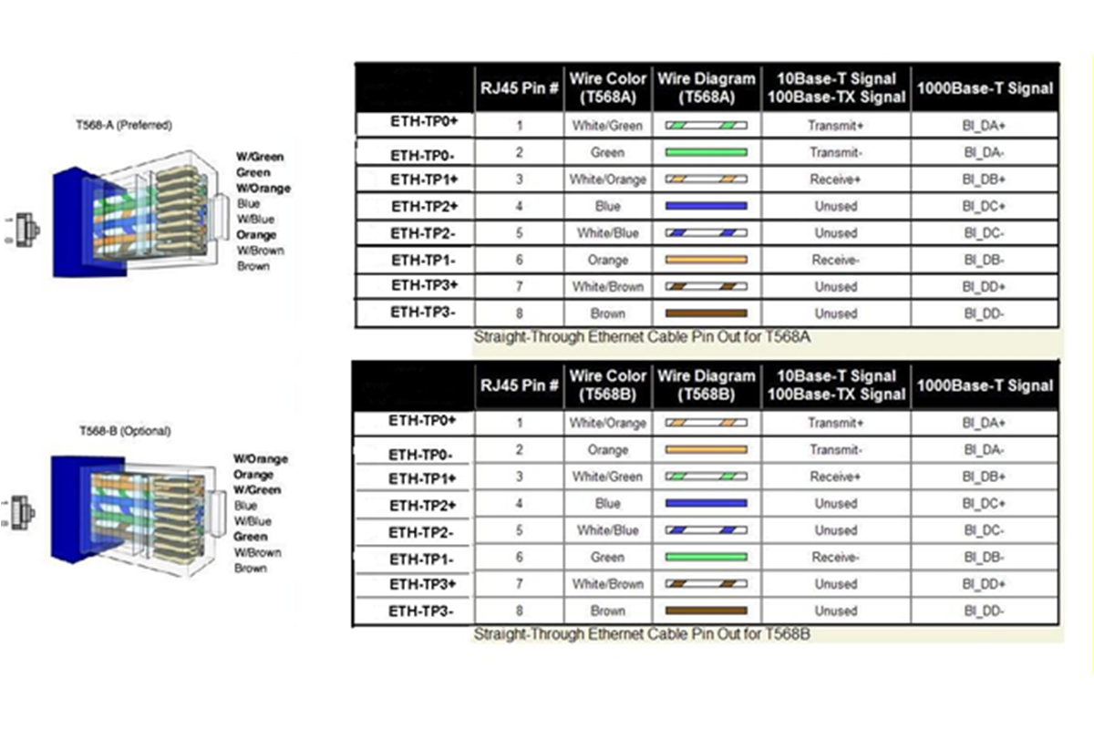
ETHERNET
For reference – available if/when the 75G5 MFIO card and the 75RTG5 is configured with the specific Ethernet options.
Table 3. Ethernet Connections
| cPCI J2 (Row-Pin) | PANEL Connector | NAI Signal | RJ-45 Standard Ethernet (REFERENCE) |
| A-02 | JP10-2 | ETH1-TP0+ | RJ-45 Port - 1 |
| B-02 | JP10-3 | ETH1-TP0- | RJ-45 Port - 2 |
| A-01 | JP10-5 | ETH1-TP1+ | RJ-45 Port - 3 |
| B-01 | JP10-6 | ETH1-TP1- | RJ-45 Port - 6 |
| D-02 | JP10-8 | ETH1-TP2+ | RJ-45 Port - 4 |
| E-02 | JP10-9 | ETH1-TP2- | RJ-45 Port - 5 |
| D-01 | JP10-11 | ETH1-TP3+ | RJ-45 Port - 7 |
| E-01 | JP10-12 | ETH1-TP3- | RJ-45 Port - 8 |
| A-04 | RJ4-3 | ETH2-TP0+ | RJ-45 Port - 1 |
| B-04 | RJ4-28 | ETH2-TP0- | RJ-45 Port - 2 |
| A-03 | RJ4-7 | ETH2-TP1+ | RJ-45 Port - 3 |
| B-03 | RJ4-32 | ETH2-TP1- | RJ-45 Port - 6 |
| D-04 | RJ4-11 | ETH2-TP2+ | RJ-45 Port - 4 |
| E-04 | RJ4-36 | ETH2-TP2- | RJ-45 Port - 5 |
| D-03 | RJ4-15 | ETH2-TP3+ | RJ-45 Port - 7 |
| E-03 | RJ4-40 | ETH2-TP3- | RJ-45 Port - 8 |
Table 4. Commercial Equivalent RJ45-type Ethernet cabling/wiring (Reference)
PART NUMBER DESIGNATION
Standard Product Part Number(s): 75RTG5-X
| X | = Configuration Options |
| 1 | = Standard pinout configuration: • All modules (MOD) configured for maximum (32-pin) I/O to RJ3, RJ4 • Single Port Gig-E (Port 1) to JP10 (utility, mini-HDMI) • RN1, RN3 installed; RN2, RN4 out (for reference only) |
| 2 | = Dual Ethernet pinout configuration: • MOD 1 & 3 maximum (32-pin) and MOD 2 standard (24-pin) I/O to RJ3, RJ4 • Dual Port Gig-E; Port 1 to JP10 (utility, mini-HDMI) and Port 2 to RJ4 ETH2-TPxx designations • RN2 installed; RN1, RN3, RN4 out (for reference only) |
| 3 | = ARM/Debug Access w/ dual rear Gig-E 75ARM1 peripheral-only (non-controller) or 75G5 Slave w/ rear Utility/Maintenance • MOD 1 maximum (32-pin) and MOD 2 & 3 standard (24-pin) I/O to RJ3, RJ4 • Dual Port Gig-E; Port 1 to JP10 (utility, mini-HDMI) and Port 2 to RJ4 ETH2-TPxx designations • Serial RS-232 debug port access provided to JP10 (utility, mini-HDMI) • ARM utility/access signals provided in lieu of MOD3 (25-32 MODIO signals) (75ARM1-peripheral ref.) 75ARM1-peripheral/75G5 debug signal references: (I2C-SCL), (I2C-SDA), (cPCI-PRSTn), (HDW-WP), (SER-TXD), (SER-RXD), (SER-GND), (RTC-STDBY) In lieu of MODIO 25-32, respectively. • RN2, RN4 installed; RN1, RN3 out (for reference only) |
| 4 | = ARM/Debug Access w/ single rear Gig-E 75ARM1 peripheral-only (non-controller) or 75G5 Slave w/ rear Utility/Maintenance • MOD 1 & 2 maximum (32-pin) and MOD 3 standard (24-pin) I/O to RJ3, RJ4 • Single Port Gig-E; Port 1 to JP10 (utility, mini-HDMI) • Serial RS-232 debug port access provided to JP10 (utility, mini-HDMI) • ARM utility/access signals provided in lieu of MOD3 (25-32 MODIO signals) 75ARM1-peripheral/75G5 debug signal references: (I2C-SCL), (I2C-SDA), (cPCI-PRSTn), (HDW-WP), (SER-TXD), (SER-RXD), (SER-GND), (RTC-STDBY) In lieu of MODIO 25-32, respectively. • RN1, RN3, RN4 installed; RN2 out (for reference only) |
| X | = Other than listed; indicates custom pinout configuration – Contact Factory |
Specifications are subject to change without notice.
REVISION HISTORY
| 75RTG5 Data Sheet Revision History | ||
| Revision | Change | Date |
| P1A | Initial Draft Release | 05/10/12 |
| P1B | Advanced release / Generic 75RTG5-1 | 06/17/14 |
| A | Agile Release | 06/18/14 |
| B | Amendments: 1. Table 2 pinout; A. Added RJ3/RJ4 references as appropriate, B. RJ4 panel I/O pins 25, 50 from GND to N/C., C. MOD1 DATIO21 from D16 to D19. 2. Reference mini HDMI mate Kit P/N corrected to 75SBC4-BB. | 09/18/15 |
| C | Added part number option dash code “4”; JP10 clarified as mini-HDMI type-C receptacle. | 10/11/16 |
| C1 | Update COSA trademarks | 3/28/17 |
DOCS.NAII REVISIONS
| Revision Date | Description |
|---|---|
| 2026-08-24 | Updated documentation to docs.naii format. |