
INTRODUCTION
As a leading manufacturer of smart function modules, NAI offers over 100 different modules that cover a wide range of I/O, measurements and simulation, communications, Ethernet switch, and SBC functions. Our CM9 combination module offers users the functionality of two COSA® smart function modules in one physical module. Based on NAI’s SC3 and AR1 modules, the CM9 module provides four RS-232/422/485 serial communications and eight ARINC 429/575 channels in a single smart function module. This user manual is designed to help you get the most out of our CM9 smart function module.
For a brief description of the module and complete list of specifications, click here for the CM9 data sheet.
CM9 Overview
NAI’s CM9 module offers a range of features designed to suit a variety of system requirements, including:
Serial Communications (SC3 Module-Type) Features
Four Communication Channels: The SC3 function offers four high-speed, programmable communication channels supporting RS232, RS-422, and RS-485 protocols. These channels can be configured as four asynchronous (async)/GPIO channels, two asynchronous channels w/Flow Control (RTS/CTS) or two synchronous (sync) channels. In Sync Mode, the module can set up clock signals (clk) on the companion pair channels (CH1-CH2 clk companion channels are CH3-CH4)
General Purpose Input/Output (GPIO): The SC3 function includes General Purpose Input/Output (GPIO) functionality, enhancing its versatility.
Data Transfer Efficiency: For asynchronous communications, data transfers occur within just two baud clocks, ensuring rapid data exchange. Synchronous communications achieve efficient data transfers in as little as 15 baud clocks.
Digital Noise Filtering: The SC3 function features digital noise filtering on receivers, enhancing signal quality and reliability.
Receiver Control: Users can selectively enable or disable specific receivers, providing fine-grained control over the communication channels.
Interrupt-Driven Operation: The SC3 function can operate in an Interrupt-Driven environment, delivering notifications of all events to the system. When flow control mode is selected, the module handles operations automatically with minimal system intervention, streamlining the communication process.
Buffer Capacity: The module boasts 1MBx16 receive and transmit buffers, ensuring ample storage for data transfer.
Built-in Test: The SC3 function comes with a built-in test feature, simplifying diagnostics and maintenance.
ARINC 429/575 (AR1 Module-Type) Features
ARINC 429: ARINC 429 is a widely adopted data transfer standard, serving as an alternative to MIL-STD-1553. It utilizes a self-clocking, self-synchronizing data bus protocol with separate transmit and receive ports. The physical connection consists of twisted pairs carrying balanced differential signaling. Each data word is 32 bits in length, with most messages containing a single data word. Messages are transmitted at either 12.5 or 100 kbps, allowing other system elements to monitor the bus messages. The transmitter continuously transmits 32-bit data words or the NULL state. A single-wire pair can accommodate one transmitter and up to 20 receivers. Notably, the receiver end of the protocol enables self-clocking, eliminating the need for transmitting clocking data.
ARINC 575: In addition to ARINC 429, the AR1 function also supports ARINC 575, a data transfer protocol specifically used for the Digital Air Data System (DADS) on commercial and transport aircraft. ARINC 575 defines a digital data bus that distributes crucial air-data information to displays, autopilots, and flight control instrumentation.
While there are minor differences between the digital data bus of ARINC 575 and ARINC 429, the most significant distinction lies in the usage of bit 32. In ARINC 429, bit 32 is reserved for parity, whereas ARINC 575 can utilize bit 32 for either parity (when using BNR encoding) or data (when using BCD encoding).
Receive/Transmit Mode Programmability: Each channel of the AR1 function can be programmed to operate in either receive or transmit mode according to your specific application needs.
Flexible Operation: The AR1 function supports both 100 kHz and 12.5 kHz operation per channel, allowing you to choose the appropriate speed for your communication requirements.
Transmit Capabilities: Enjoy the convenience of a 255 message FIFO or scheduled transmits per channel, allowing you to efficiently manage and control the transmission of messages. Additionally, asynchronous transmits can be performed alongside scheduled transmits.
Receive Capabilities: Benefit from a 255 message FIFO or mailbox buffering per channel, providing ample storage for incoming messages. This ensures reliable reception and efficient handling of data.
Message Validation: The AR1 function supports SDI/Label Filtering, enabling you to validate received messages based on specific criteria per channel. This feature enhances the overall data integrity and ensures only relevant information is processed.
Hardware Parity: You have the option to enable selectable hardware parity generation/checking, which adds an extra layer of data integrity verification during transmission and reception.
Receive Time Stamping: Gain valuable insight into message reception with the functions’ receive time stamping feature. This allows precise timing analysis and synchronization in your communication system.
Continuous Built-In Test (BIT): The AR1 function incorporates continuous BIT functionality, providing self-diagnostics and monitoring capabilities to ensure reliable operation and easy troubleshooting.
Loop-Back Test: Verify the integrity of the AR1 function by performing loop-back tests. This feature allows you to validate the communication path and confirm proper functionality.
Tri-State Outputs: The AR1 function’s outputs support tri-state functionality, allowing you to control the state of the outputs as needed. This enables seamless integration with other system components.
High and Low-Speed Slew Rate Outputs: The AR1 function offers both high and low-speed slew rate outputs, providing flexibility in meeting the requirements of various communication interfaces.
SC3 FUNCTION
Principle of Operation
The CM9 provides (4) channels of programmable serial communication buses (SC3 module-type). Each channel of the module can be individually software configured for RS-232C, RS-422 or RS-485 Asynchronous/Synchronous Serial Communications or GPIO. See CM9 module pinout tables for more specific pinouts between modes. The architecture avoids latency problems because all data transfer is done in hardware and not in software. Any incoming data, no matter how many channels are active, in whatever mode, can be immediately extracted. FPGA design simplifies programming and usage.
Configuration
Before the user can write to any configuration register, certain steps must be followed to ensure the module accepts the user specified configuration. The steps are as follows:
-
Write a 0 to the Enable Channel bit of the Tx-Rx Configuration register to tell the hardware that we are about to change the configuration.
-
Wait for the Channel Configured status of the Realtime Channel Status registers to read a 0.
-
Write all desired configuration registers.
-
Set the Enable Channel bit of the Tx-Rx Configuration register to 1 to notify the hardware that it can read all the configuration registers.
-
Wait for the Channel Configured status in the Realtime Channel Status register to read a 1 before proceeding to send/receive data.
Async/Sync Modes
All four channels can be configured in asynchronous mode or the first two channels can be configured for synchronous modes. Mixing asynchronous and synchronous modes is also possible.
Sync Mode Channel Pairs
The user can configure any of the first two channels of the SC3 function to operate in any of the following synchronous modes: HDLC, Mono-Synchronous or Bi-Synchronous. When any of these channels are configured for a synchronous mode, the channel will need to pair with another channel to make sue of its transmitter and receiver to handle clock input and output signals. Channel pairs are as follows: 1&3, 2&4.
Hardware Flow Control
The user can configure any of the first two channels of the SC3 function to operate in hardware flow control mode by setting the RTS/CTS Flow Control bit of the Tx-Rx Configuration register to a 1. When a channel is configured in this mode, the channel pair’s transmitter and receiver will be used for the Request to Send (RTS) and Clear to Send (CTS) signals. The channels pairs are the same as in sync mode.
GPIO Mode
The SC3 function is configured for GPIO mode via the Interface Levels register. Setting the GPIO bit to 1, sets a channel to GPIO mode. It is also necessary to choose either RS-232 or RS-422 to determine the GPIO signal level.
Note
As shown in the CM9 module pinout tables, single ended RS-232 provides GPI 1, GPI 2, GPO1 and GPO 2. RS-422 provides GPI 1 and GPO 1 only.
To set an output (GPO) channel to a high state, set the Channel Control register RTS/GPO 1 or GPO 2 bits, to 1. The default is 0 (low). Inputs (GPI) are monitored by the Dynamic Status register, bits CTS/GPI 1 and GPI 2, which provide real-time status monitoring of the GPI inputs. The Latched Status register, bits CTS/GPI 1 and GPI 2, latch when an input is received and are cleared when a 1 is written to the register. The Interrupt Enable register bits CTS/GPI 1 and GPI 2 when set to a 1, will create an interrupt. To invert the GPI/GPO inputs and outputs, set the Tx-Rx Configuration register bits Invert CTS (GPI) and Invert RTS (GPO), to 1. See the Register Descriptions for more information.
Gap Timeout Status
The Gap Timeout Occurred status gets set when there’s data in a channel’s receive buffer but there’s no activity on a channel’s receiver for approximately three byte-times. To use the Gap Timeout feature, set the Enable Gap Timeout bit in the Tx-Rx Configuration register to a 1. When receiving asynchronous data, monitor the Gap Timeout status bit of the Channel Status register to know if a timeout occurred. The status is cleared after all the data in the receive buffer is read or cleared.
Serial Built-In Test/Diagnostic Capability
The SC3 function supports two types of built-in tests: Power-On and Initiated. The results of these tests are logically ORed together and stored in the BIT Dynamic Status and BIT Latched Status registers.
Power-on Self-Test (POST)/Power-on BIT (PBIT)/Start-up BIT (SBIT)
The power-on self-test is performed on each channel automatically when power is applied and report the results in the BIT Status register when complete. After power-on, the Power-on BIT Complete register should be checked to ensure that POST/PBIT/SBIT test is complete before reading the BIT Dynamic Status and BIT Latched Status registers.
Initiated Built-In Test
The Initiated Built-In-Test (IBIT) is an internal loopback available for each channel of the SC3 module. The test is initiated by setting the bit for the associated channel in the Test Enabled register or (for legacy applications) setting the Initiate BIT bit of the Tx-Rx-Configuration register to a 1. Prior to initiating the test, the user must disable the channel, and its respective pair, by writing a 0 to the Enable Channel bit of the channel’s Tx-Rx Configuration register. BIT will not run if the channel is enabled. After the user disables the channel and initiates BIT, they must wait a minimum of 5 msec then check to see if the bit for the associated channel in the Test Enabled register or (for legacy application) Initiate BIT bit of the Tx-Rx-Configuration register reads a 0. When the SC3 clears the bit, it means that the test has completed, and its results can be checked. If the bit has not cleared after 10ms, the test has timed out and not run. In the event this should occur, the user should verify that the channel, and its pair, has been disabled. The results of the IBIT is stored in the BIT Dynamic Status and BIT Latched Status registers, a 0 indicates that the channel has passed and a 1 indicates that it failed.
Receiver Enable/Disable
A Receiver Enable/Disable function allows the user to turn selected receivers ON/OFF. When a receiver is disabled, no data will be placed in the buffer.
Serial Data Transmit Enhancement
An additional asynchronous mode to support “Immediate Transmit” operation has been incorporated. This mode immediately transmits serial data anytime the transmit buffer is not empty. There is no requirement to set the Tx Initiate bit before each transmission, which simplifies system traffic and overhead, since only the actual data byte being transmitted needs be sent to the transmit buffer. Each channel has its own configurable Transmit and Receive buffer. The upper byte of each received word provides status information for that word.
Multi-Drop Link Mode (RS485)
The transmitter and receivers of up to 32 channels can be tied together in either Half or Full-Duplex mode. While in Multi-Drop Link Mode, the transmit line for each channel will automatically tri-state. When data in the transmit buffer is initiated, the transmitter will be taken out of tri-state and send the data. Once transmission is completed, the transmit line is automatically changed back to tri-state mode. To program the serial channel for Multi-Drop mode, the interface level must be set to RS485, and the Tristate Transmit Line bit in the Channel Control register must be set to a 1.
Communication Module Factory Defaults: Registers and Delays
| Address Recognition: | Off |
| Baud Rate: | 9600 |
| CTS/RTS: | Disabled |
| Protocol: | 0, Asynchronous |
| Interface Levels: | 0 |
| Termination Character: | 0x0003 |
| Interrupt Level: | 0 |
| Interrupt Vector: | 0x00 |
| Mode: | Asynchronous |
| Number of Data Bits: | 8 |
| Parity: | Disabled |
| Receivers: | Disabled |
| Transmit Buffer Word Count: | 0 |
| Receive Buffer Word Count: | 0 |
| Receive Buffer, Almost Full: | 0xFFF9B |
| Stop Bits: | 1 |
| Transmit Buffer, Almost Empty: | 0x0100 |
| Tx-Rx Configuration: | 0 |
| Channel Control: | 0 |
| Data Configuration: | 0x0108 |
| Preamble: | 0 |
| Receive Buffer High Watermark: | 0xFFF9B |
| Receive Buffer Low Watermark: | 0x0800 |
| XON: | 0 |
| XOFF: | 0 |
| XON/XOFF: | Disabled |
| Time Out Value: | 0x9C40 |
A write to the following registers takes place immediately:
- Transmit Data
- Channel Control
- Channel Interrupt Enable
- Channel Interrupt Edge/Level
- Summary Interrupt Enable
- Summary Edge/Level
- Interrupt Vector
- Interrupt Steering
For all other registers, channel configuration protocol must be followed.
Status and Interrupts
The SC3 Serial Communications function provide registers that indicate faults or events. Refer to “Status and Interrupts Module Manual” for the Principle of Operation description.
Module Common Registers
The SC3 Serial Communications function includes module common registers that provide access to module-level bare metal/FPGA revisions & compile times, unique serial number information, and temperature/voltage/current monitoring. Refer to “Module Common Registers Module Manual” for the detailed information.
Register Descriptions
The register descriptions provide the register name, Type, Data Range, Read or Write information, Initialized Value, a description of the function and, in most cases, a data table.
Receive Registers
Serial data received are placed in the Receive FIFO Buffer register. The Receive FIFO Buffer Word Count provide the count of the number of elements in the Receive FIFO Buffer. The Receive FIFO Buffer Almost Full, Receive FIFO Buffer High Watermark and Receive FIFO Buffer Low Watermark registers provide the ability to specify the thresholds for the associated status in the Channel FIFO Status register.
Receive FIFO Buffer
| Receive FIFO Buffer | |
| Function: | Received data is placed in this buffer. |
| Type: | unsigned binary word (32-bit). |
| Data Range: | 0x 0000 0000 to 0x 0000 FFFF |
| Read/Write: | R |
| Initialized Value: | N/A |
| Operational Settings: | Data is received is based on Protocol. |
Note
Receive FIFO Buffer is a self-clearing register. Performing a register read of the Receive FIFO marks the current location as ‘read’. This moves the pointer to the next unread location and decrements the Receive FIFO Buffer Word Count register count by one.
| Asynchronous/Asynchronous-GPI | |||||||||||||||
| D31 | D30 | D29 | D28 | D27 | D26 | D25 | D24 | D23 | D22 | D21 | D20 | D19 | D18 | D17 | D16 |
| 0 | 0 | 0 | 0 | 0 | 0 | 0 | 0 | 0 | 0 | 0 | 0 | 0 | 0 | 0 | 0 |
| D15 | D14 | D13 | D12 | D11 | D10 | D9 | D8 | D7 | D6 | D5 | D4 | D3 | D2 | D1 | D0 |
| PE | FE | 0 | 0 | 0 | EOF | P | D | D | D | D | D | D | D | D | D |
| Bi-Synchronous/Mono-Synchronous | |||||||||||||||
| D31 | D30 | D29 | D28 | D27 | D26 | D25 | D24 | D23 | D22 | D21 | D20 | D19 | D18 | D17 | D16 |
| 0 | 0 | 0 | 0 | 0 | 0 | 0 | 0 | 0 | 0 | 0 | 0 | 0 | 0 | 0 | 0 |
| D15 | D14 | D13 | D12 | D11 | D10 | D9 | D8 | D7 | D6 | D5 | D4 | D3 | D2 | D1 | D0 |
| 0 | 0 | 0 | 0 | 0 | 0 | EOF | 0 | D | D | D | D | D | D | D | D |
| HDLC | |||||||||||||||
| D31 | D30 | D29 | D28 | D27 | D26 | D25 | D24 | D23 | D22 | D21 | D20 | D19 | D18 | D17 | D16 |
| 0 | 0 | 0 | 0 | 0 | 0 | 0 | 0 | 0 | 0 | 0 | 0 | 0 | 0 | 0 | 0 |
| D15 | D14 | D13 | D12 | D11 | D10 | D9 | D8 | D7 | D6 | D5 | D4 | D3 | D2 | D1 | D0 |
| 0 | BOF | 0 | ER2 | ER1 | ER0 | EOF | 0 | D | D | D | D | D | D | D | D |
| Asynchronous/Asynchronous-GPI | ||
| PE | = Parity Error | A 1 indicates the calculated parity does not match the received parity bit. |
| FE | = Framing Error | A 1 indicates a framing error was detected. |
| EOF | = End of Frame | A 1 indicates an ETx character was received. Termination Character Detection must be turned on. |
| P | = Parity Bit | This bit carries the parity bit of the last received character. |
| Bi-Synchronous/Mono-Synchronous | ||
| EOF | = End of Frame | A 1 indicates the End of Frame. Useful to identify multiple frames in large buffer. |
| HDLC | ||
| BOF | = Beginning of Frame | A 1 indicates first character of frame. Useful to identify multiple frames in large buffer. |
| EOF | = End of Frame | A 1 indicates End of Frame. Useful to identify multiple frames in large buffer. |
| ER2:ER0 | = Last Frame Status | 000 = Good Frame 111 = CRC Error |
| Receive FIFO Buffer Word Count | |
| Function: | Contains the number of words in the Receive FIFO Buffer waiting to be read back. |
| Type: | unsigned binary word (32-bits) |
| Data Range: | 0 to 0x0010 0000 (Buffer Size) |
| Read/Write: | R |
| Initialized Value: | 0 |
| Operational Settings: | Reads Integers. |
| Receive FIFO Almost Full | |
| Function: | Contains the number of words in the Receive FIFO Buffer waiting to be read back. Specifies the maximum size, in bytes, of the receive buffer before the Receive FIFO Almost Full Status bit D0 in the FIFO Status register is flagged (High True). |
| Type: | unsigned binary word (32-bits) |
| Data Range: | 0 to 0x0010 0000 (Buffer Size) |
| Read/Write: | R/W |
| Initialized Value: | 1048475 (0x000F FF9B) |
| Operational Settings: | If the interrupt is enabled (see Interrupt Enable register), a System interrupt will be generated. |
| Receive FIFO Buffer High Watermark | |
| Function: | Defines the Receive Buffer High Watermark value. |
| Type: | unsigned binary word (32-bits) |
| Data Range: | Low Watermark < High Watermark < 0xFFF9B |
| Read/Write: | R/W |
| Initialized Value: | 1048475 (0xFFF9B) |
| Operational Settings: | When Receive FIFO Buffer size equals the High Watermark value, the High Watermark bit in both the FIFO Status and Channel Status registers is set to a 1 and: * If XON/XOFF is enabled, XOFF is sent, and/or * If RTS/CTS is enabled, RTS goes inactive. The Watermark registers are used for XON/XOFF and/or RTS/CTS flow control. The Receive Buffer High Watermark register value controls when the XOFF character is sent when using software flow control and controls when the RTS signal would be negated when using hardware flow control. For software flow control operation, the XOFF character would be sent once when the number of bytes in the Receive FIFO Buffer equals the value in the Receive Buffer High Watermark register. Once the XOFF has been sent, it cannot be sent again until the XON character has been sent. The valid state transitions to sending the XOFF character can be either no previous XON/XOFF character sent or a previous XON character sent. There is also a High Watermark Reached interrupt enable/disable bit in the Channel Interrupt Enable register and a High Watermark Reached bit in the Channel Interrupt Status Register. When the High Watermark is reached, an interrupt request will be generated, when the interrupt enable/disable bit is enabled. |
| Receive FIFO Buffer Low Watermark | |
| Function: | Defines the Receive Buffer Low Watermark value. |
| Type: | unsigned binary word (32-bits) |
| Data Range: | 0 < Low Watermark < High Watermark < 0xFFF9B |
| Read/Write: | R/W |
| Initialized Value: | 2048 (0x0800) |
| Operational Settings: | When Receive Buffer size equals the Low Watermark value, the Low Watermark bit in both the FIFO Status and Channel Status registers is set to a 1 and: * If XON/XOFF is enabled, XON is sent, and/or * If RTS/CTS is enabled, RTS goes active. The Watermark registers are used for XON/XOFF and/or RTS/CTS flow control. The Receive Buffer Low Watermark register value controls when the XON character is sent when using software flow control and controls when the RTS signal would be asserted when using hardware flow control. For software flow control operation, the XON character would be sent once when the number of bytes in the Receive FIFO Buffer equals the value in the Receive Buffer Low Watermark register AND an XOFF character has been sent prior to this XON character. The valid state transition to sending the XON character can only be from the state of a previous XOFF character that has been sent. There is a Low Watermark Reached interrupt enable/disable bit in the Channel Interrupt Enable register and a Low Watermark Reached bit in the Channel Interrupt Status Register. When the Low Watermark is reached, an interrupt request will be generated, when the interrupt enable/disable bit is enabled. |
Transmit Registers
Serial data to be transmitted are placed in the Transmit FIFO Buffer register. The Transmit FIFO Buffer Word Count provides the count of the number of elements in the Transmit FIFO Buffer. The Receive FIFO Buffer Almost Empty register provide the ability to specify the threshold for the associated status in the Channel FIFO Status register.
| Transmit FIFO Buffer | |
| Function: | Data to be transmitted is placed in this buffer prior to transmission. |
| Type: | unsigned binary word (32-bits) |
| Data Range: | 0x 0000 0000 to 0x 0000 01FF |
| Read/Write: | W |
| Initialized Value: | N/A |
| Operational Settings: | Data words are 8-bit and occupy the register's lowest significant bits (LSBs), or low byte. |
| D31 | D30 | D29 | D28 | D27 | D26 | D25 | D24 | D23 | D22 | D21 | D20 | D19 | D18 | D17 | D16 |
| 0 | 0 | 0 | 0 | 0 | 0 | 0 | 0 | 0 | 0 | 0 | 0 | 0 | 0 | 0 | 0 |
| D15 | D14 | D13 | D12 | D11 | D10 | D9 | D8 | D7 | D6 | D5 | D4 | D3 | D2 | D1 | D0 |
| 0 | 0 | 0 | 0 | 0 | 0 | 0 | D | D | D | D | D | D | D | D | D |
| Transmit FIFO Buffer Word Count | |
| Function: | Contains the number of words in the Transmit FIFO Buffer waiting to be transmitted. |
| Type: | unsigned binary word (32-bits) |
| Data Range: | 0 to 0x0010 0000 (Buffer Size) |
| Read/Write: | R |
| Initialized Value: | 0 |
| Transmit FIFO Buffer Almost Empty | |
| Function: | Specifies the minimum size, in bytes, of the transmit buffer before the Transmit Buffer Almost Empty Status bit D1 in the FIFO Status register is flagged (High True). |
| Type: | unsigned binary word (32-bits) |
| Data Range: | 0 to 0x0010 0000 (Buffer Size) |
| Read/Write: | R/W |
| Initialized Value: | 256 (0x100) |
| Operational Settings: | If the interrupt is enabled (see Interrupt Enable register), a System interrupt will be generated. |
Configuration Registers
SC3 configurations includes setting the Interface Levels, Baud Rate, Protocol, Tx-Rx Configuration and if applicable, the Termination Character registers. Additional registers need to be configured specifically for Async or Sync modes.
| Interface Levels | |
| Function: | Configures the interface level (RS-232, RS-422, RS-485, Loopback, Tri-State, FPGA Loop-Back, GPIO) for the associated channel. |
| Type: | unsigned binary word (32-bits) |
| Data Range: | See table |
| Read/Write: | R/W |
| Initialized Value: | 0x0000 0000 |
| Operational Settings: | Loopback selection connects the channel's transmit and receive line internally. To implement, user must send data and look at Receive FIFO to verify that the sent data. Loopback is usually used for testing. Note: Channels are programmed for loop back in pairs. For example, if channel 1 is programmed for loop back, then channel 2 will be also. This includes channels 3 and 4. |
| Bit(s) | Interface | Description |
| D31:D15 | Reserved | Set Reserved bits to 0. |
| D14 | GPIO | Needs to be ORed with either RS232 or RS422. |
| D13:D8 | Reserved | Set Reserved bits to 0. |
| D7 | Disable termination resistor | Disables termination resistor in-between the differential pairs of the transmitter and the receiver. Useful for RS485 Multi-Drop. |
| D6:D3 | Reserved | Set Reserved bits to 0. |
| D2:D0 | Interface Level | These bits set the interface level: (0:0:0) RS232 (0:1:0) RS422 (0:1:1) RS485 (1:0:0) Loopback (1:0:1) Tri-State |
| Baud Rate | |
| Function: | Sets the baud rate for communications. |
| Type: | unsigned binary word (32-bits) |
| Data Range: | 300 bps to 10 Mbps Sync (1.5 Mbps Async) |
| Read/Write: | R/W |
| Initialized Value: | 0x2580 (9600 bps) |
| Protocol | |
| Function: | Configures the associated channel for either asynchronous, mono-synchronous, bi-synchronous, HDLC mode or mixed asynchronous and GPIO modes. |
| Type: | unsigned binary word (32-bits) |
| Data Range: | See table |
| Read/Write: | R/W |
| Initialized Value: | 0 (Asynchronous) |
| Operational Settings: | See table below. |
| Bit(s) | Protocol | Description |
| D31:D6 | Reserved | Set Reserved bits to 0. |
| D5:D0 | 0x00 - Async 0x01 - Mono-Synchronous 0x02 - Bi-Synchronous 0x03 - HDLC 0x10 - Async-GPO 0x20 - Async-GPI | Async-GPO: This mode can transmit general purpose signals on the channels transmitter while being able to receive async serial data on the receiver. Async-GPI: This mode can transmit async serial data on the channels transmitter while being able to receive general purpose signals on the receiver. |
| Tx-Rx Configuration | |
| Function: | Sets the transmit/receive configuration for the associated channel. |
| Type: | unsigned binary word (32-bits) |
| Data Range: | See table |
| Read/Write: | R/W |
| Initialized Value: | 0 |
| Operational Settings: | BIT - Set Enable Channel bit, D24 low (0) to clear the selected channel. Set Initiate BIT bit D27 high (1) to initiate BIT. After 5 msec, a 0 should be read, which indicates that the BIT test is complete. The BIT Status register reports the channel status. |
| Bit(s) | Name | Description |
| D31:D28 | Reserved | Set Reserved bits to 0. |
| D27 | Initiate BIT | Write a 1 to start built-in-test. The channel running BIT needs to be disabled, as well as it's channel pair. For common module functionality see the Test Enabled register. |
| D26 | Invert RTS/GPO | 0 = Normal 1 = Invert |
| D25 | Invert CTS/GPI | 0 = Normal 1 = Invert |
| D24 | Enable Channel | 0 = Disable 1 = Enable |
| D23 | Rx Suppression | 0 = Receiver Always On 1 = Receiver Off During Transmission (RS485 only) |
| D22 | Reserved | Set Reserved bits to 0. |
| D21 | Idle Flag | Idle Flag (0x7E) Transmission |
| D20 | Enable Gap Timeout | 0 = Ignore gap timeout 1 = Set Gap Timeout Occurred status when there is no activity on the receiver's bus for more than 3-byte times. |
| D19 | Append CRC | 0 = No CRC 1 = Append CRC to Tx Data, Expect CRC with Rx data |
| D18:D17 | CRC | (0:0) 16-Bit CRC (Mono/Bi-Sync only) (0:1) 32-Bit CRC (HDLC only) (1:0) 16-Bit CCITT |
| D16 | CRC Reset Value | 0 = Ones 1 = Zeros |
| D15 | Timeout Detection | Turns on timeout detection |
| D14 | XON/XOFF Char as Data | 0 = Stripped 1 = Keep in data |
| D13 | XON/XOFF Flow Control | Turns on Software Flow Control |
| D12 | Termination Character Detection | 0 = Ignore termination character 1 = Set Rx Complete/ETx Received status bit when termination character is received. |
| D11 | Sync char as data | 0 = Stripped 1 = Keep in data |
| D10:D8 | Reserved | Set Reserved bits to 0. |
| D7 | Address Length | 0 = 8 bits 1 = 16 bits |
| D6:D4 | Address Transmission/Recognition (HLDC only): 0x0 - Addressing Off 0x1 - Rx Address Recognition only 0x2 - Tx Address Transmission only 0x4 - Addressing On | Addressing Off: Don't send address, receive data from any address. Rx Address Recognition: Expect address on Rx, but don't send address. Tx Address Transmission: Send address, but don't expect it. Addressing On: Send and expect address. |
| D3:D1 | Reserved | Set Reserved bits to 0. |
| D0 | RTS/CTS Flow Control | Turns on Hardware Flow Control |
| Termination Character | |
| Function: | Contains the termination character used for termination detection. |
| Type: | unsigned character (usually a member of the ASCII data set) |
| Data Range: | 0x00 to 0xFF |
| Read/Write: | R/W |
| Initialized Value: | 0x03 |
| Operational Settings: | When using the Asynchronous or Mono/Bi-Synchronous modes, the receive data stream is monitored for the occurrence of the termination character. When this character is detected, the Rx COMPLETE / ETx RECEIVED bit is set in the Channel Status register, an interrupt is generated, if enabled. |
Async Only Configuration
In Async mode, additional configurations include setting the Data Configuration, Time Out Value, XOFF Character and XON Character registers.
| Data Configuration | |
| Function: | Channel data configuration. |
| Type: | unsigned binary word (32-bits) |
| Data Range: | See table |
| Read/Write: | R/W |
| Initialized Value: | 0x108 |
| Operational Settings: | Sets up the Serial channel configuration. |
| Bit(s) | Name | Description |
| D31:D15 | Reserved | Set Reserved bits to 0. |
| D14:D12 | Encoding | The following sets the Data Encoding: (0:0:0) No Encoding (NRZ) (1:1:0) Manchester (GE Thomas) (1:1:1) Manchester (IEEE 802.3) |
| D11:D10 | Reserved | Set Reserved bits to 0. |
| D9:D8 | Stop Bits | The following sets the number of stop bits: (0:1) 1 Stop bit (1:0) 2 Stop bits |
| D7 | Reserved | Set Reserved bits to 0. |
| D6:D4 | Parity | The following sets the Parity: (0:0:0) No Parity (0:0:1) Space Parity (0:1:0) Reserved (0:1:1) Odd Parity (1:0:0) Reserved (1:0:1) Even Parity (1:1:1) Mark Parity |
| D3:D0 | Number of Data Bits | Actual number of data bits between 5 and 9. For Asynchronous Protocol only. |
| Time Out Value | |
| Function: | Determines the timeout period. |
| Type: | unsigned binary word (32-bits) |
| Data Range: | 0 to 0xFFFF |
| Read/Write: | R/W |
| Initialized Value: | 0x9C40 (1 second) |
| Operational Settings: | If there is no receive line activity for the configured period of time, a timeout is indicated in the Interrupt Status register, bit D10. LSB is 25µs. Modes Affected: Async. |
| XON Character | |
| Function: | Specifies the XON character for asynchronous flow control mode. |
| Type: | unsigned binary word 32-bits (usually a member of the ASCII data set) |
| Data Range: | 0x00 to 0xFF |
| Read/Write: | R/W |
| Initialized Value: | 0 |
| Modes Affected: | Async |
| Operational Settings: | When software flow control is enabled, this value is sent as the XON character. |
| XOFF Character | |
| Function: | Specifies the XOFF character for asynchronous software flow control mode. |
| Type: | unsigned binary word 32-bits (usually a member of the ASCII data set) |
| Data Range: | 0x00 to 0xFF |
| Read/Write: | R/W |
| Initialized Value: | 0 |
| Modes Affected: | Async |
| Operational Settings: | When software flow control is enabled, this value is sent as the XOFF character. |
Sync Only Configuration
In Sync mode, additional configurations include setting the Clock Mode, HDLC Rx Address/Sync Character and HDLC Tx Address/Sync Character registers.
| Clock Mode | |
| Function: | Configures clock for internal (driven) or external (received) transmit/receive clocks |
| Type: | unsigned binary word (32-bits) |
| Data Range: | See table. |
| Read/Write: | R/W |
| Initialized Value: | 0 |
| Operational Settings: | Applicable only for Mono/bi-synchronous or HDLC as set by Protocol register. |
| Default: | 0 |
| Bit(s) | Name | Description |
| D31:D8 | Reserved | Set Reserved bits to 0. |
| D7 | Invert Rx Clock | Swap receive clock edge. |
| D6 | Invert Tx Clock | Swap transmit clock edge. |
| D5 | Tristate Clock after Tx | |
| D4:D2 | Reserved | Set Reserved bits to 0. |
| D1:D0 | 0x0: Internal 0x1: External 0x2: Tx-Internal, Rx-External 0x3: Reserved | Internal: Module always drives clock. External: Module always receives clock. Tx-Internal, Rx-External: Module drives clock for Tx, Module receives clock for Rx. |
| HDLC Rx Address/Sync Character | |
| Function: | Mode dependent for HDLC and Synchronous modes. See Operational Settings. |
| Type: | unsigned binary word (32-bits) |
| Data Range: | 0x0000 to 0xFFFF |
| Read/Write: | R/W |
| Initialized Value: | 0x0000 0000 |
| Operational Settings: | HDLC Mode: This value is compared to the address of the received message and if it's equal, the message is stored in the receive buffer. Mono/Bi-Synchronous Mode: this value is considered the “Sync Character” and is used for communication synchronization. The receiver searches incoming data for the Sync Character. Once found, communication is synchronized, and additional data is valid. When in Bi-Synchronous, low byte is sent before high byte. |
| HDLC | |||||||||||||||
| D31 | D30 | D29 | D28 | D27 | D26 | D25 | D24 | D23 | D22 | D21 | D20 | D19 | D18 | D17 | D16 |
| 0 | 0 | 0 | 0 | 0 | 0 | 0 | 0 | 0 | 0 | 0 | 0 | 0 | 0 | 0 | 0 |
| D15 | D14 | D13 | D12 | D11 | D10 | D9 | D8 | D7 | D6 | D5 | D4 | D3 | D2 | D1 | D0 |
| 0 | 0 | 0 | 0 | 0 | 0 | 0 | 0 | 8-bit address when Address Length bit in Tx-Rx Configuration register is 0. | |||||||
| 16-bit address when Address Length bit in Tx-Rx Configuration register is 1. | |||||||||||||||
| Mono-Synchronous | |||||||||||||||
| D31 | D30 | D29 | D28 | D27 | D26 | D25 | D24 | D23 | D22 | D21 | D20 | D19 | D18 | D17 | D16 |
| 0 | 0 | 0 | 0 | 0 | 0 | 0 | 0 | 0 | 0 | 0 | 0 | 0 | 0 | 0 | 0 |
| D15 | D14 | D13 | D12 | D11 | D10 | D9 | D8 | D7 | D6 | D5 | D4 | D3 | D2 | D1 | D0 |
| 0 | 0 | 0 | 0 | 0 | 0 | 0 | 0 | 8-bit synchronization character | |||||||
| Bi-Synchronous | |||||||||||||||
| D31 | D30 | D29 | D28 | D27 | D26 | D25 | D24 | D23 | D22 | D21 | D20 | D19 | D18 | D17 | D16 |
| 0 | 0 | 0 | 0 | 0 | 0 | 0 | 0 | 0 | 0 | 0 | 0 | 0 | 0 | 0 | 0 |
| D15 | D14 | D13 | D12 | D11 | D10 | D9 | D8 | D7 | D6 | D5 | D4 | D3 | D2 | D1 | D0 |
| Second 8-bit synchronization character | First 8-bit synchronization character | ||||||||||||||
| HDLC Tx Address/Sync Character | |
| Function: | Mode dependent for HDLC and Synchronous modes. See Operational Settings. |
| Type: | unsigned binary word (32-bits) |
| Data Range: | 0x0000 to 0xFFFF |
| Read/Write: | R/W |
| Initialized Value: | 0x0000 0000 |
| Operational Settings: | If using HDLC Mode: this value is compared to the address of the received message and if it's equal, the message is stored in the receive buffer. Mono/Bi-Synchronous Mode: this value is considered the “Sync Character” and is used for communication synchronization. The receiver searches incoming data for the Sync Character. Once found, communication is synchronized, and additional data is valid. When in Bi-Synchronous, low byte is sent before high byte. |
| Preamble | |
| Function: | Determines the number of preambles and the preamble pattern sent during a preamble transmission. |
| Type: | unsigned binary word (32-bits) |
| Data Range: | 0x0000 to 0x70FF |
| Read/Write: | R/W |
| Initialized Value: | 0 |
| Operational Settings: | In HDLC Mode: zero-bit insertion is disabled during preamble transmission. |
| Bit(s) | Name | Description |
| D31:D15 | Reserved | Set Reserved bits to 0. |
| D14:D12 | Number of Preambles | The number of Preamble Patterns to be sent. |
| D11:D8 | Reserved | Set Reserved bits to 0. |
| D7:D0 | Preamble Pattern | Actual data byte to be sent. |
Control Register
The Channel Control register provides control of the serial channel.
| Channel Control | |
| Function: | Channel control configuration. |
| Type: | unsigned binary word (32-bits) |
| Data Range: | See table. |
| Read/Write: | R/W |
| Initialized Value: | 0 |
| Operational Settings: | Real time control of the Serial channel. |
| Bit(s) | Name | Description |
| D31:D19 | Reserved | Set Reserved bits to 0. |
| D18 | Enable Receiver | |
| D17 | Tx Always (Async Only) | Transmit data as soon as data is buffered. |
| D16 | Tx Initiate | Transmit data in Tx buffer. (The data bit is cleared when all data from the Tx Buffer is transmitted) |
| D15 | Clear Tx FIFO | Clear all data in the Tx FIFO. The data bit is self-clearing. |
| D14 | Clear Rx FIFO | Clear all data in the Rx FIFO. The data bit is self-clearing. |
| D13 | Reset Channel FIFOs & UART | Clear both FIFOs and reset channel. Bit is not self-clearing. |
| D12:D11 | Reserved | Set Reserved bits to 0. |
| D10 | Set/Release Break | 0 = Break not set 1 = Pull transmitter low |
| D9 | Reserved | Set Reserved bits to 0. |
| D8 | Tristate Transmit Line | Tristate the transmit line after transmitting, for use with RS485 Multi-Drop mode. |
| D7:D2 | Reserved | Set Reserved bits to 0. |
| D1 | GPO 2 | General purpose output two control. |
| D0 | RTS/GPO 1* | General purpose output one control. |
Note
*RTS/CTS as GPO when RTS/CTS Flow Control disabled.
Serial Test Registers
The serial module provides the ability to run an initiated test (IBIT). Writing a 1 to the bit associated with the channel in the Test Enabled register.
Note
This register has the same effect as writing a 1 to the Initiate BIT bit of the Tx-Rx Configuration register for legacy applications.
| Test Enabled | |
| Function: | Set the bit corresponding to the channel you want to run Initiated Built-In-Test. |
| Type: | unsigned binary word (32-bit) |
| Data Range: | 0 to 0x0000 000F |
| Read/Write: | R/W |
| Initialized Value: | 0x0 |
| Operational Settings: | Set bit to 1 for channel to run an Initiated BIT test. Failures in the BIT test are reflected in the BIT Status registers for the corresponding channels that fail. In addition, an interrupt (if enabled in the BIT Interrupt Enable register) can be triggered when the BIT testing detects failures. Bit is self-clearing. |
| D31 | D30 | D29 | D28 | D27 | D26 | D25 | D24 | D23 | D22 | D21 | D20 | D19 | D18 | D17 | D16 |
| 0 | 0 | 0 | 0 | 0 | 0 | 0 | 0 | 0 | 0 | 0 | 0 | 0 | 0 | 0 | 0 |
| D15 | D14 | D13 | D12 | D11 | D10 | D9 | D8 | D7 | D6 | D5 | D4 | D3 | D2 | D1 | D0 |
| 0 | 0 | 0 | 0 | 0 | 0 | 0 | 0 | 0 | 0 | 0 | 0 | Ch4 | Ch3 | Ch2 | Ch1 |
Background BIT Threshold Programming Registers
The Background BIT Threshold register provides the ability to specify the minimum time before the BIT fault is reported in the BIT Status registers. The Reset BIT register provides the ability to reset the BIT counter used in CBIT.
| Background BIT Threshold | |
| Function: | Sets background BIT Threshold value to use for all channels for BIT failure indication. This value is a scalar for the internal BIT counter, refer to Continuous Background Built-In Test. To filter out momentary or intermittent anomalies in background BIT errors, this value can be increased to allow the error to “come and go” before the BIT status is flagged. |
| Data Range: | 0x1 to 0xFFFF |
| Read/Write: | R/W |
| Initialized Value: | 5 |
| Reset BIT | |
| Function: | Resets the CBIT internal circuitry and count mechanism. Set the bit corresponding to the channel you want to clear. |
| Type: | unsigned binary word (32-bit) |
| Data Range: | 0 to 0x0000 000F |
| Read/Write: | W |
| Initialized Value: | 0 |
| Operational Settings: | Set bit to 1 for channel to resets the CBIT mechanisms. Bit is self-clearing. |
| D31 | D30 | D29 | D28 | D27 | D26 | D25 | D24 | D23 | D22 | D21 | D20 | D19 | D18 | D17 | D16 |
| 0 | 0 | 0 | 0 | 0 | 0 | 0 | 0 | 0 | 0 | 0 | 0 | 0 | 0 | 0 | 0 |
| D15 | D14 | D13 | D12 | D11 | D10 | D9 | D8 | D7 | D6 | D5 | D4 | D3 | D2 | D1 | D0 |
| 0 | 0 | 0 | 0 | 0 | 0 | 0 | 0 | 0 | 0 | 0 | 0 | Ch4 | Ch3 | Ch2 | Ch1 |
Module Common Registers
Refer to “Module Common Registers Module Manual” for the register descriptions.
Status and Interrupt Registers
The SC3 Module provides status registers for BIT, Channel, Summary and Channel FIFO.
BIT Status
There are four registers associated with the BIT Status: Dynamic Status, Latched Status, Interrupt Enable, and Set Edge/Level Interrupt.
| BIT Status | |
| Function: | Sets the corresponding bit associated with the channel's BIT error. |
| Type: | unsigned binary word (32-bits) |
| Data Range: | 0x0000 0000 to 0x00FF 000F |
| Read/Write: | R (Dynamic), R/W (Latched, Interrupt Enable, Edge/Level Interrupt) |
| Initialized Value: | 0 |
Note
BIT Status is a shared register between the SC3 and AR1 functions. Bits D3:D0 are dedicated to the SC3 function and bits D23:D16 are dedicated to the AR1 function.
| BIT Dynamic Status | |||||||||||||||
| BIT Latched Status | |||||||||||||||
| BIT Interrupt Enable | |||||||||||||||
| BIT Set Edge/Level Interrupt | |||||||||||||||
| D31 | D30 | D29 | D28 | D27 | D26 | D25 | D24 | D23 | D22 | D21 | D20 | D19 | D18 | D17 | D16 |
| 0 | 0 | 0 | 0 | 0 | 0 | 0 | 0 | AR1 Ch8 | AR1 Ch7 | AR1 Ch6 | AR1 Ch5 | AR1 Ch4 | AR1 Ch3 | AR1 Ch2 | AR1 Ch1 |
| D15 | D14 | D13 | D12 | D11 | D10 | D9 | D8 | D7 | D6 | D5 | D4 | D3 | D2 | D1 | D0 |
| 0 | 0 | 0 | 0 | 0 | 0 | 0 | 0 | 0 | 0 | 0 | 0 | SC3 Ch4 | SC3 Ch3 | SC3 Ch2 | SC3 Ch1 |
Power-on BIT (PBIT) Complete
After power-on, the Power-on BIT Complete register should be checked to ensure that POST/PBIT/SBIT test is complete before reading the BIT Dynamic Status and BIT Latched Status registers.
| Power-on BIT (PBIT) Complete | |
| Function: | Indication if Power-on BIT has completed. |
| Type: | unsigned binary word (32-bits) |
| Data Range: | 0x0000 0000 to 0x0000 0001 |
| Read/Write: | R |
| Initialized Value: | 0 |
| D31 | D30 | D29 | D28 | D27 | D26 | D25 | D24 | D23 | D22 | D21 | D20 | D19 | D18 | D17 | D16 |
| 0 | 0 | 0 | 0 | 0 | 0 | 0 | 0 | 0 | 0 | 0 | 0 | 0 | 0 | 0 | 0 |
| D15 | D14 | D13 | D12 | D11 | D10 | D9 | D8 | D7 | D6 | D5 | D4 | D3 | D2 | D1 | D0 |
| 0 | 0 | 0 | 0 | 0 | 0 | 0 | 0 | 0 | 0 | 0 | 0 | 0 | 0 | 0 | PBIT Complete |
Channel Status
There are four registers associated with the Channel Status: Dynamic Status, Latched Status, Interrupt Enable, and Set Edge/Level Interrupt.
| Channel Status | |
| Function: | Sets the corresponding bit associated with each event type. There are separate registers for each channel. |
| Type: | unsigned binary word (32-bits) |
| Data Range: | See table. |
| Read/Write: | R (Dynamic), R/W (Latched, Interrupt Enable, Set Edge/Level Interrupt) |
| Initialized Value: | 0 |
| Channel Dynamic Status | |||
| Channel Latched Status | |||
| Channel Interrupt Enable | |||
| Channel Set Edge/Level Interrupt | |||
| Bit(s) | Name | Configurable | Description |
| D31 | Channel Configured | No | Module is configured and ready to operate. |
| D30 | Built-in-Self Test Passed | No | Indicates the status of the last ran IBIT test. |
| D29:D18 | Reserved | No | Set Reserved bits to 0. |
| D17 | Gap Timeout Occurred | Yes | Rx FIFO has data in it, but there hasn't been activity on the bus in 3-byte times. |
| D16 | GPI 2 | No | Binary value of general-purpose input 2. |
| D15 | CTS/GPI1 | No | Binary value of general-purpose input 1 or CTS. |
| D14 | CTS Low Detect (fall) | No | CTS falling edge detected. |
| D13 | CTS High Detect (rise) | No | CTS rising edge detected. |
| D12 | Reserved | No | Set Reserved bits to 0. |
| D11 | Break/Abort | No | Break recognized. |
| D10 | Timeout Occurred | Yes | No receive line activity within timeout value. |
| D9 | Tx Complete | No | While transmitting, Tx FIFO count reaches zero. |
| D8 | Tx FIFO Almost Empty | Yes | Transmit FIFO Almost Empty Threshold reached. |
| D7 | Low Watermark Reached | Yes | Rx Buffer Low Watermark Threshold reached. |
| D6 | High Watermark Reached | Yes | Rx Buffer High Watermark Threshold reached. |
| D5 | Rx Overrun | No | Data was received while the Rx FIFO was full. |
| D4 | Rx Data Available | No | Receive FIFO count is greater than zero. |
| D3 | Rx Complete/ET x Received | No | Async: Termination character received (Only if termination detection is turned on.) HDLC: End of frame flag detected. Mono/Bi-Sync: Termination character received. |
| D2 | CRC Error (Sync & HDLC) | No | CRC calculation did not match. |
| D1 | Rx FIFO Almost Full | Yes | Receive FIFO Almost Full Threshold |
| D0 | Parity Error | No | Parity bit did not match. |
Note
For the Latched Channel Status register, the interrupts are cleared when a 1 is written to the specific bit.
FIFO Status
There are four registers associated with the FIFO Status: Dynamic, Latched, Interrupt Enable, and Set Edge/Level Interrupt. D0-D5 is used to show the different conditions of the buffer.
| FIFO Status | |
| Function: | Describes current FIFO Status. |
| Type: | unsigned binary word (32-bits) |
| Data Range: | See Table |
| Read/Write: | R |
| Initialized Value: | 0 |
| Operational Settings: | See Rx Almost Full, Tx Almost Empty, Rx High Watermark and Rx Low Watermark specific registers for function description and programming. |
| Bit(s) | Name | Configurable? | Description |
| D5 | Tx FIFO Full | No | Tx FIFO has reached maximum buffer size. |
| D4 | Rx FIFO Empty | No | Rx FIFO count is zero. |
| D3 | Low Watermark Reached | Yes | Rx Buffer Low Watermark Threshold reached. |
| D2 | High Watermark Reached | Yes | Rx Buffer High Watermark Threshold reached. |
| D1 | Tx FIFO Almost Empty | Yes | Tx FIFO Almost Empty Threshold reached. |
| D0 | Rx FIFO Almost Full | Yes | Rx FIFO Almost Full Threshold reached |
| D31 | D30 | D29 | D28 | D27 | D26 | D25 | D24 | D23 | D22 | D21 | D20 | D19 | D18 | D17 | D16 |
| 0 | 0 | 0 | 0 | 0 | 0 | 0 | 0 | 0 | 0 | 0 | 0 | 0 | 0 | 0 | 0 |
| D15 | D14 | D13 | D12 | D11 | D10 | D9 | D8 | D7 | D6 | D5 | D4 | D3 | D2 | D1 | D0 |
| 0 | 0 | 0 | 0 | 0 | 0 | 0 | 0 | 0 | 0 | D | D | D | D | D | D |
Summary Status
There are four registers associated with the Summary Status: Dynamic, Latched, Interrupt Enable, and Set Edge/Level Interrupt.
| Summary Status | |
| Function: | Sets the corresponding bit if any fault (BIT or Inter-FPGA Failure) occurs on that channel. |
| Type: | unsigned binary word (32-bit) |
| Data Range: | 0x0000 0000 to 0x00FF 000F |
| Read/Write: | R (Dynamic), R/W (Latched, Interrupt Enable, Edge/Level Interrupt) |
| Initialized Value: | 0 |
Note
Summary Status is a shared register between the SC3 and AR1 functions. Bits D3:D0 are dedicated to the SC3 function and bits D23:D16 are dedicated to the AR1 function.
| Summary Dynamic Status | |||||||||||||||
| Summary Latched Status | |||||||||||||||
| Summary Interrupt Enable | |||||||||||||||
| Summary Set Edge/Level Interrupt | |||||||||||||||
| D31 | D30 | D29 | D28 | D27 | D26 | D25 | D24 | D23 | D22 | D21 | D20 | D19 | D18 | D17 | D16 |
| 0 | 0 | 0 | 0 | 0 | 0 | 0 | 0 | AR1 Ch8 | AR1 Ch7 | AR1 Ch6 | AR1 Ch5 | AR1 Ch4 | AR1 Ch3 | AR1 Ch2 | AR1 Ch1 |
| D15 | D14 | D13 | D12 | D11 | D10 | D9 | D8 | D7 | D6 | D5 | D4 | D3 | D2 | D1 | D0 |
| 0 | 0 | 0 | 0 | 0 | 0 | 0 | 0 | 0 | 0 | 0 | 0 | SC3 Ch4 | SC3 Ch3 | SC3 Ch2 | SC3 Ch1 |
WDT & Inter-FPGA Failure Status
The WDT & Inter-FPGA Failure status set reports module watchdog-timer and inter-FPGA communication failure conditions, including the Bus Hang Timeout condition. There are four registers associated with the User Watchdog Timer Fault/Inter-FPGA Failure Status: Dynamic, Latched, Interrupt Enable, and Set Edge/Level Interrupt.
Note
WDT & Inter-FPGA Failure Status is a shared register between the SC3 and AR1 functions.
| WDT & Bus Hang Timeout & Inter-FPGA Failure Status | |
| Function: | Sets the corresponding bit (D30) associated with the channel's Bus Hang Timeout condition. |
| Type: | unsigned binary word (32-bit) |
| Data Range: | 0x0000 0000 to 0x4000 0000 |
| Read/Write: | R (Dynamic), R/W (Latched, Interrupt Enable, Edge/Level Interrupt) |
| Initialized Value: | 0 |
| User Watchdog Timer Fault & Inter-FPGA Failure Dynamic Status | |||||||||||||||
| User Watchdog Timer Fault & Inter-FPGA Failure Latched Status | |||||||||||||||
| User Watchdog Timer Fault & Inter-FPGA Failure Interrupt Enable | |||||||||||||||
| User Watchdog Timer Fault & Inter-FPGA Failure Set Edge/Level Interrupt | |||||||||||||||
| D31 | D30 | D29 | D28 | D27 | D26 | D25 | D24 | D23 | D22 | D21 | D20 | D19 | D18 | D17 | D16 |
| 0 | Hang Timeout | 0 | 0 | 0 | 0 | 0 | 0 | 0 | 0 | 0 | 0 | 0 | 0 | 0 | 0 |
| D15 | D14 | D13 | D12 | D11 | D10 | D9 | D8 | D7 | D6 | D5 | D4 | D3 | D2 | D1 | D0 |
| 0 | 0 | 0 | 0 | 0 | 0 | 0 | 0 | 0 | 0 | 0 | 0 | 0 | 0 | 0 | 0 |
Interrupt Vector and Steering
When interrupts are enabled, the interrupt vector associated with the specific interrupt can be programmed (typically with a unique number/identifier) such that it can be utilized in the Interrupt Service Routine (ISR) to identify the type of interrupt. When an interrupt occurs, the contents of the Interrupt Vector registers is reported as part of the interrupt mechanism. In addition to specifying the interrupt vector, the interrupt can be directed (“steered”) to the native bus or to the application running on the onboard ARM processor.
Note
The Interrupt Vector and Interrupt Steering registers are mapped to the Motherboard Common Memory and these registers are associated with the Module Slot position (refer to Function Register Map).
| Interrupt Vector | |
| Function: | Set an identifier for the interrupt. |
| Type: | unsigned binary word (32-bit) |
| Data Range: | 0x0000 0000 to 0xFFFF FFFF |
| Read/Write: | R/W |
| Initialized Value: | 0 |
| Operational Settings: | When an interrupt occurs, this value is reported as part of the interrupt mechanism. |
| Interrupt Steering | |
| Function: | Sets where to direct the interrupt. |
| Type: | unsigned binary word (32-bit) |
| Data Range: | See table Read/Write: R/W |
| Initialized Value: | 0 |
| Operational Settings: | When an interrupt occurs, the interrupt is sent as specified: |
| Direct Interrupt to VME | 1 |
| Direct Interrupt to ARM Processor (via SerDes) (Custom App on ARM or NAI Ethernet Listener App) | 2 |
| Direct Interrupt to PCIe Bus | 5 |
| Direct Interrupt to cPCI Bus | 6 |
Function Register Map
KEY
| Incoming Data |
| Outgoing Data |
| Configuration/Control |
| Status |
| RECEIVE REGISTERS | |||||
| NOTE: Base Address - 0x4000 0000 | |||||
| OFFSET | REGISTER NAME | ACCESS | OFFSET | REGISTER NAME | ACCESS |
| 0x1004 | Receive FIFO Buffer Ch 1 | R | 0x100C | Receive FIFO Buffer Word Count Ch 1 | R |
| 0x1084 | Receive FIFO Buffer Ch 2 | R | 0x108C | Receive FIFO Buffer Word Count Ch 2 | R |
| 0x1104 | Receive FIFO Buffer Ch 3 | R | 0x110C | Receive FIFO Buffer Word Count Ch 3 | R |
| 0x1184 | Receive FIFO Buffer Ch 4 | R | 0x118C | Receive FIFO Buffer Word Count Ch 4 | R |
| 0x1034 | Receive FIFO Buffer Almost Full Ch 1 | R/W | 0x1038 | Receive FIFO Buffer High Watermark Ch 1 | R/W |
| 0x10B4 | Receive FIFO Buffer Almost Full Ch 2 | R/W | 0x10B8 | Receive FIFO Buffer High Watermark Ch 2 | R/W |
| 0x1134 | Receive FIFO Buffer Almost Full Ch 3 | R/W | 0x1138 | Receive FIFO Buffer High Watermark Ch 3 | R/W |
| 0x11B4 | Receive FIFO Buffer Almost Full Ch 4 | R/W | 0x11B8 | Receive FIFO Buffer High Watermark Ch 4 | R/W |
| 0x103C | Receive FIFO Buffer Low Watermark Ch 1 | R/W | |||
| 0x10BC | Receive FIFO Buffer Low Watermark Ch 2 | R/W | |||
| 0x113C | Receive FIFO Buffer Low Watermark Ch 3 | R/W | |||
| 0x11BC | Receive FIFO Buffer Low Watermark Ch 4 | R/W | |||
| TRANSMIT REGISTERS | |||||
| NOTE: Base Address - 0x4000 0000 | |||||
| OFFSET | REGISTER NAME | ACCESS | OFFSET | REGISTER NAME | ACCESS |
| 0x1000 | Transmit FIFO Buffer Ch 1 | W | 0x1008 | Transmit FIFO Buffer Word Count Ch 1 | R |
| 0x1080 | Transmit FIFO Buffer Ch 2 | W | 0x1088 | Transmit FIFO Buffer Word Count Ch 2 | R |
| 0x1100 | Transmit FIFO Buffer Ch 3 | W | 0x1108 | Transmit FIFO Buffer Word Count Ch 3 | R |
| 0x1180 | Transmit FIFO Buffer Ch 4 | W | 0x1188 | Transmit FIFO Buffer Word Count Ch 4 | R |
| 0x1030 | Transmit FIFO Buffer Almost Empty Ch 1 | R/W | |||
| 0x10B0 | Transmit FIFO Buffer Almost Empty Ch 2 | R/W | |||
| 0x1130 | Transmit FIFO Buffer Almost Empty Ch 3 | R/W | |||
| 0x11B0 | Transmit FIFO Buffer Almost Empty Ch 4 | R/W | |||
| CONFIGURATION REGISTERS | |||||
| NOTE: Base Address - 0x4000 0000 | |||||
| OFFSET | REGISTER NAME | ACCESS | OFFSET | REGISTER NAME | ACCESS |
| 0x1018 | Interface Levels Ch 1 | R/W | 0x1028 | Baud Rate Ch 1 | R/W |
| 0x1098 | Interface Levels Ch 2 | R/W | 0x10A8 | Baud Rate Ch 2 | R/W |
| 0x1118 | Interface Levels Ch 3 | R/W | 0x1128 | Baud Rate Ch 3 | R/W |
| 0x1198 | Interface Levels Ch 4 | R/W | 0x11A8 | Baud Rate Ch 4 | R/W |
| 0x1010 | Protocol Ch 1 | R/W | 0x101C | Tx-Rx Configuration Ch 1 | R/W |
| 0x1090 | Protocol Ch 2 | R/W | 0x109C | Tx-Rx Configuration Ch 2 | R/W |
| 0x1110 | Protocol Ch 3 | R/W | 0x111C | Tx-Rx Configuration Ch 3 | R/W |
| 0x1190 | Protocol Ch 4 | R/W | 0x119C | Tx-Rx Configuration Ch 4 | R/W |
| 0x1050 | Termination Character Ch 1 | R/W | |||
| 0x10D0 | Termination Character Ch 2 | R/W | |||
| 0x1150 | Termination Character Ch 3 | R/W | |||
| 0x11D0 | Termination Character Ch 4 | R/W | |||
| ASYNC ONLY CONFIGURATION REGISTERS | |||||
| NOTE: Base Address - 0x4000 0000 | |||||
| OFFSET | REGISTER NAME | ACCESS | OFFSET | REGISTER NAME | ACCESS |
| 0x1024 | Data Configuration Ch 1 | R/W | 0x1054 | Time Out Value Ch 1 | R/W |
| 0x10A4 | Data Configuration Ch 2 | R/W | 0x10D4 | Time Out Value Ch 2 | R/W |
| 0x1124 | Data Configuration Ch 3 | R/W | 0x1154 | Time Out Value Ch 3 | R/W |
| 0x11A4 | Data Configuration Ch 4 | R/W | 0x11D4 | Time Out Value Ch 4 | R/W |
| 0x1048 | XON Character Ch 1 | R/W | 0x104C | XOFF Character Ch 1 | R/W |
| 0x10C8 | XON Character Ch 2 | R/W | 0x10CC | XOFF Character Ch 2 | R/W |
| 0x1148 | XON Character Ch 3 | R/W | 0x114C | XOFF Character Ch 3 | R/W |
| 0x11C8 | XON Character Ch 4 | R/W | 0x11CC | XOFF Character Ch 4 | R/W |
| SYNC ONLY CONFIGURATION REGISTERS | |||||
| NOTE: Base Address - 0x4000 0000 | |||||
| OFFSET | REGISTER NAME | ACCESS | OFFSET | REGISTER NAME | ACCESS |
| 0x1014 | Clock Mode Ch 1 | R/W | 0x1040 | HDLC Rx Address/Sync Character Ch 1 | R/W |
| 0x1094 | Clock Mode Ch 2 | R/W | 0x10C0 | HDLC Rx Address/Sync Character Ch 2 | R/W |
| 0x1114 | Clock Mode Ch 3 | R/W | 0x1140 | HDLC Rx Address/Sync Character Ch 3 | R/W |
| 0x1194 | Clock Mode Ch 4 | R/W | 0x11C0 | HDLC Rx Address/Sync Character Ch 4 | R/W |
| 0x1044 | HDLC Tx Address/Sync Character Ch 1 | R/W | 0x102C | Preamble Ch 1 | R/W |
| 0x10C4 | HDLC Tx Address/Sync Character Ch 2 | R/W | 0x10AC | Preamble Ch 2 | R/W |
| 0x1144 | HDLC Tx Address/Sync Character Ch 3 | R/W | 0x112C | Preamble Ch 3 | R/W |
| 0x11C4 | HDLC Tx Address/Sync Character Ch 4 | R/W | 0x11AC | Preamble Ch 4 | R/W |
| CONTROL REGISTERS | |||||
| NOTE: Base Address - 0x4000 0000 | |||||
| OFFSET | REGISTER NAME | ACCESS | OFFSET | REGISTER NAME | ACCESS |
| 0x1020 | Channel Control Ch 1 | R/W | |||
| 0x10A0 | Channel Control Ch 2 | R/W | |||
| 0x1120 | Channel Control Ch 3 | R/W | |||
| 0x11A0 | Channel Control Ch 4 | R/W | |||
| BIT REGISTERS | |||||
| *When an event is detected, the bit associated with the event is set in this register and will remain set until the user clears the event bit. Clearing the bit requires writing a 1 back to the specific bit that was set when read (i.e., write-1-to-clear, writing a “1” to a bit set to “1” will set the bit to “0). | |||||
| NOTE: Base Address - 0x4000 0000 | |||||
| OFFSET | REGISTER NAME | ACCESS | OFFSET | REGISTER NAME | ACCESS |
| 0x0800 | Dynamic Status | R | |||
| 0x0804 | Latched Status* | R/W | |||
| 0x0808 | Interrupt Enable | R/W | |||
| 0x080C | Set Edge/Level Interrupt | R/W | |||
| NOTE: Base Address - 0x4000 0000 | |||||
| 0x0248 | Test Enabled | R/W | 0x02AC | Power-on BIT Complete++ | R |
| 0x02B8 | Background BIT Threshold | R/W | 0x02BC | Reset BIT | W |
| ++After power-on, Power-on BIT Complete should be checked before reading the BIT Latched Status. | |||||
| CHANNEL STATUS REGISTERS | |||||
| *When an event is detected, the bit associated with the event is set in this register and will remain set until the user clears the event bit. Clearing the bit requires writing a 1 back to the specific bit that was set when read (i.e., write-1-to-clear, writing a “1” to a bit set to “1” will set the bit to “0). | |||||
| NOTE: Base Address - 0x4000 0000 | |||||
| OFFSET | REGISTER NAME | ACCESS | OFFSET | REGISTER NAME | ACCESS |
| 0x0810 | Channel Dynamic Status Ch 1 | R | 0x0820 | Channel Dynamic Status Ch 2 | R |
| 0x0814 | Channel Latched Status Ch 1* | R/W | 0x0824 | Channel Latched Status Ch 2* | R/W |
| 0x0818 | Channel Interrupt Enable Ch 1 | R/W | 0x0828 | Channel Interrupt Enable Ch 2 | R/W |
| 0x081C | Channel Set Edge/Level Interrupt Ch 1 | R/W | 0x082C | Channel Set Edge/Level Interrupt Ch 2 | R/W |
| 0x0830 | Channel Dynamic Status Ch 3 | R | 0x0840 | Channel Dynamic Status Ch 4 | R |
| 0x0834 | Channel Latched Status Ch 3* | R/W | 0x0844 | Channel Latched Status Ch 4* | R/W |
| 0x0838 | Channel Interrupt Enable Ch 3 | R/W | 0x0848 | Channel Interrupt Enable Ch 4 | R/W |
| 0x083C | Channel Set Edge/Level Interrupt Ch 3 | R/W | 0x084C | Channel Set Edge/Level Interrupt Ch 4 | R/W |
| FIFO STATUS REGISTERS | |||||
| NOTE: Base Address - 0x4000 0000 | |||||
| OFFSET | REGISTER NAME | ACCESS | OFFSET | REGISTER NAME | ACCESS |
| 0x1058 | FIFO Status Ch 1 | R | |||
| 0x10D8 | FIFO Status Ch 2 | R | |||
| 0x1158 | FIFO Status Ch 3 | R | |||
| 0x11D8 | FIFO Status Ch 4 | R | |||
| SUMMARY STATUS REGISTERS | |||||
| *When an event is detected, the bit associated with the event is set in this register and will remain set until the user clears the event bit. Clearing the bit requires writing a 1 back to the specific bit that was set when read (i.e., write-1-to-clear, writing a “1” to a bit set to “1” will set the bit to “0). | |||||
| NOTE: Base Address - 0x4000 0000 | |||||
| OFFSET | REGISTER NAME | ACCESS | OFFSET | REGISTER NAME | ACCESS |
| 0x09A0 | Dynamic Status | R | |||
| 0x09A4 | Latched Status* | R/W | |||
| 0x09A8 | Interrupt Enable | R/W | |||
| 0x09AC | Set Edge/Level Interrupt | R/W | |||
| WDT & INTER-FPGA FAILURE STATUS REGISTERS | |||||
| *When an event is detected, the bit associated with the event is set in this register and will remain set until the user clears the event bit. Clearing the bit requires writing a 1 back to the specific bit that was set when read (i.e., write-1-to-clear, writing a “1” to a bit set to “1” will set the bit to “0). | |||||
| NOTE: Base Address - 0x4000 0000 | |||||
| OFFSET | REGISTER NAME | ACCESS | OFFSET | REGISTER NAME | ACCESS |
| 0x09B0 | Dynamic Status | R | |||
| 0x09B4 | Latched Status* | R/W | |||
| 0x09B8 | Interrupt Enable | R/W | |||
| 0x09BC | Set Edge/Level Interrupt | R/W | |||
| INTERRUPT REGISTERS | |||||
| The Interrupt Vector and Interrupt Steering registers are located on the Motherboard Memory Space and do not require any Module Address Offsets. These registers are accessed using the absolute addresses listed in the table below. NOTE: Vector/Steering 2-5 are allocated for the Serial (SC3) function; vector/steering 6-13 are allocated for the ARINC 429/575 (AR1) function. | |||||
| OFFSET | REGISTER NAME | ACCESS | OFFSET | REGISTER NAME | ACCESS |
| 0x0500 | Module 1 Interrupt Vector 1 - BIT | R/W | 0x0600 | Module 1 Interrupt Steering 1 - BIT | R/W |
| 0x0504 | Module 1 Interrupt Vector 2 - Serial Channel Status Ch 1 | R/W | 0x0604 | Module 1 Interrupt Steering 2 - Serial Channel Status Ch 1 | R/W |
| 0x0508 | Module 1 Interrupt Vector 3 - Serial Channel Status Ch 2 | R/W | 0x0608 | Module 1 Interrupt Steering 3 - Serial Channel Status Ch 2 | R/W |
| 0x050C | Module 1 Interrupt Vector 4 - Serial Channel Status Ch 3 | R/W | 0x060C | Module 1 Interrupt Steering 4 - Serial Channel Status Ch 3 | R/W |
| 0x0510 | Module 1 Interrupt Vector 5 - Serial Channel Status Ch 4 | R/W | 0x0610 | Module 1 Interrupt Steering 5 - Serial Channel Status Ch 4 | R/W |
| 0x0514 | Module 1 Interrupt Vector 6 - AR1 Channel Status Ch 1 | R/W | 0x0614 | Module 1 Interrupt Steering 6 - AR1 Channel Status Ch 1 | R/W |
| 0x0518 | Module 1 Interrupt Vector 7 - AR1 Channel Status Ch 2 | R/W | 0x0618 | Module 1 Interrupt Steering 7 - AR1 Channel Status Ch 2 | R/W |
| 0x051C | Module 1 Interrupt Vector 8 - AR1 Channel Status Ch 3 | R/W | 0x061C | Module 1 Interrupt Steering 8 - AR1 Channel Status Ch 3 | R/W |
| 0x0520 | Module 1 Interrupt Vector 9 - AR1 Channel Status Ch 4 | R/W | 0x0620 | Module 1 Interrupt Steering 9 - AR1 Channel Status Ch 4 | R/W |
| 0x0524 | Module 1 Interrupt Vector 10 - AR1 Channel Status Ch 5 | R/W | 0x0624 | Module 1 Interrupt Steering 10 - AR1 Channel Status Ch 5 | R/W |
| 0x0528 | Module 1 Interrupt Vector 11 - AR1 Channel Status Ch 6 | R/W | 0x0628 | Module 1 Interrupt Steering 11 - AR1 Channel Status Ch 6 | R/W |
| 0x052C | Module 1 Interrupt Vector 12 - AR1 Channel Status Ch 7 | R/W | 0x062C | Module 1 Interrupt Steering 12 - AR1 Channel Status Ch 7 | R/W |
| 0x0530 | Module 1 Interrupt Vector 13 - AR1 Channel Status Ch 8 | R/W | 0x0630 | Module 1 Interrupt Steering 13 - AR1 Channel Status Ch 8 | R/W |
| 0x0534 to 0x0564 | Module 1 Interrupt Vector 14 to 26 - Reserved | R/W | 0x0634 to 0x0664 | Module 1 Interrupt Steering 14 to 26 - Reserved | R/W |
| 0x0568 | Module 1 Interrupt Vector 27 - Summary Status | R/W | 0x0668 | Module 1 Interrupt Steering 27 - Summary Status | R/W |
| 0x056C | Module 1 Interrupt Vector 28 - WDT & Inter-FPGA Failure | R/W | 0x066C | Module 1 Interrupt Steering 28 - WDT & Inter-FPGA Failure | R/W |
| 0x0570 to 0x057C | Module 1 Interrupt Vector 29 to 32 - Reserved | R/W | 0x0670 to 0x067C | Module 1 Interrupt Steering 29 to 32 - Reserved | R/W |
| 0x0700 | Module 2 Interrupt Vector 1 - BIT | R/W | 0x0800 | Module 2 Interrupt Steering 1 - BIT | R/W |
| 0x0704 | Module 2 Interrupt Vector 2 - Serial Channel Status Ch 1 | R/W | 0x0804 | Module 2 Interrupt Steering 2 - Serial Channel Status Ch 1 | R/W |
| 0x0708 | Module 2 Interrupt Vector 3 - Serial Channel Status Ch 2 | R/W | 0x0808 | Module 2 Interrupt Steering 3 - Serial Channel Status Ch 2 | R/W |
| 0x070C | Module 2 Interrupt Vector 4 - Serial Channel Status Ch 3 | R/W | 0x080C | Module 2 Interrupt Steering 4 - Serial Channel Status Ch 3 | R/W |
| 0x0710 | Module 2 Interrupt Vector 5 - Serial Channel Status Ch 4 | R/W | 0x0810 | Module 2 Interrupt Steering 5 - Serial Channel Status Ch 4 | R/W |
| 0x0714 | Module 2 Interrupt Vector 6 - AR1 Channel Status Ch 1 | R/W | 0x0814 | Module 2 Interrupt Steering 6 - AR1 Channel Status Ch 1 | R/W |
| 0x0718 | Module 2 Interrupt Vector 7 - AR1 Channel Status Ch 2 | R/W | 0x0818 | Module 2 Interrupt Steering 7 - AR1 Channel Status Ch 2 | R/W |
| 0x071C | Module 2 Interrupt Vector 8 - AR1 Channel Status Ch 3 | R/W | 0x081C | Module 2 Interrupt Steering 8 - AR1 Channel Status Ch 3 | R/W |
| 0x0720 | Module 2 Interrupt Vector 9 - AR1 Channel Status Ch 4 | R/W | 0x0820 | Module 2 Interrupt Steering 9 - AR1 Channel Status Ch 4 | R/W |
| 0x0724 | Module 2 Interrupt Vector 10 - AR1 Channel Status Ch 5 | R/W | 0x0824 | Module 2 Interrupt Steering 10 - AR1 Channel Status Ch 5 | R/W |
| 0x0728 | Module 2 Interrupt Vector 11 - AR1 Channel Status Ch 6 | R/W | 0x0828 | Module 2 Interrupt Steering 11 - AR1 Channel Status Ch 6 | R/W |
| 0x072C | Module 2 Interrupt Vector 12 - AR1 Channel Status Ch 7 | R/W | 0x082C | Module 2 Interrupt Steering 12 - AR1 Channel Status Ch 7 | R/W |
| 0x0730 | Module 2 Interrupt Vector 13 - AR1 Channel Status Ch 8 | R/W | 0x0830 | Module 2 Interrupt Steering 13 - AR1 Channel Status Ch 8 | R/W |
| 0x0734 to 0x0764 | Module 2 Interrupt Vector 14 to 26 - Reserved | R/W | 0x0834 to 0x0864 | Module 2 Interrupt Steering 14 to 26 - Reserved | R/W |
| 0x0768 | Module 2 Interrupt Vector 27 - Summary Status | R/W | 0x0868 | Module 2 Interrupt Steering 27 - Summary Status | R/W |
| 0x076C | Module 2 Interrupt Vector 28 - WDT & Inter-FPGA Failure | R/W | 0x086C | Module 2 Interrupt Steering 28 - WDT & Inter-FPGA Failure | R/W |
| 0x0770 to 0x077C | Module 2 Interrupt Vector 29 to 32 - Reserved | R/W | 0x0870 to 0x087C | Module 2 Interrupt Steering 29 to 32 - Reserved | R/W |
| 0x0900 | Module 3 Interrupt Vector 1 - BIT | R/W | 0x0A00 | Module 3 Interrupt Steering 1 - BIT | R/W |
| 0x0904 | Module 3 Interrupt Vector 2 - Serial Channel Status Ch 1 | R/W | 0x0A04 | Module 3 Interrupt Steering 2 - Serial Channel Status Ch 1 | R/W |
| 0x0908 | Module 3 Interrupt Vector 3 - Serial Channel Status Ch 2 | R/W | 0x0A08 | Module 3 Interrupt Steering 3 - Serial Channel Status Ch 2 | R/W |
| 0x090C | Module 3 Interrupt Vector 4 - Serial Channel Status Ch 3 | R/W | 0x0A0C | Module 3 Interrupt Steering 4 - Serial Channel Status Ch 3 | R/W |
| 0x0910 | Module 3 Interrupt Vector 5 - Serial Channel Status Ch 4 | R/W | 0x0A10 | Module 3 Interrupt Steering 5 - Serial Channel Status Ch 4 | R/W |
| 0x0914 | Module 3 Interrupt Vector 6 - AR1 Channel Status Ch 1 | R/W | 0x0A14 | Module 3 Interrupt Steering 6 - AR1 Channel Status Ch 1 | R/W |
| 0x0918 | Module 3 Interrupt Vector 7 - AR1 Channel Status Ch 2 | R/W | 0x0A18 | Module 3 Interrupt Steering 7 - AR1 Channel Status Ch 2 | R/W |
| 0x091C | Module 3 Interrupt Vector 8 - AR1 Channel Status Ch 3 | R/W | 0x0A1C | Module 3 Interrupt Steering 8 - AR1 Channel Status Ch 3 | R/W |
| 0x0920 | Module 3 Interrupt Vector 9 - AR1 Channel Status Ch 4 | R/W | 0x0A20 | Module 3 Interrupt Steering 9 - AR1 Channel Status Ch 4 | R/W |
| 0x0924 | Module 3 Interrupt Vector 10 - AR1 Channel Status Ch 5 | R/W | 0x0A24 | Module 3 Interrupt Steering 10 - AR1 Channel Status Ch 5 | R/W |
| 0x0928 | Module 3 Interrupt Vector 11 - AR1 Channel Status Ch 6 | R/W | 0x0A28 | Module 3 Interrupt Steering 11 - AR1 Channel Status Ch 6 | R/W |
| 0x092C | Module 3 Interrupt Vector 12 - AR1 Channel Status Ch 7 | R/W | 0x0A2C | Module 3 Interrupt Steering 12 - AR1 Channel Status Ch 7 | R/W |
| 0x0930 | Module 3 Interrupt Vector 13 - AR1 Channel Status Ch 8 | R/W | 0x0A30 | Module 3 Interrupt Steering 13 - AR1 Channel Status Ch 8 | R/W |
| 0x0934 to 0x0964 | Module 3 Interrupt Vector 14 to 26 - Reserved | R/W | 0x0A34 to 0x0A64 | Module 3 Interrupt Steering 14 to 26 - Reserved | R/W |
| 0x0968 | Module 3 Interrupt Vector 27 - Summary Status | R/W | 0x0A68 | Module 3 Interrupt Steering 27 - Summary Status | R/W |
| 0x096C | Module 3 Interrupt Vector 28 - WDT & Inter-FPGA Failure | R/W | 0x0A6C | Module 3 Interrupt Steering 28 - WDT & Inter-FPGA Failure | R/W |
| 0x0970 to 0x097C | Module 3 Interrupt Vector 29 to 32 - Reserved | R/W | 0x0A70 to 0x0A7C | Module 3 Interrupt Steering 29 to 32 - Reserved | R/W |
| 0x0B00 | Module 4 Interrupt Vector 1 - BIT | R/W | 0x0C00 | Module 4 Interrupt Steering 1 - BIT | R/W |
| 0x0B04 | Module 4 Interrupt Vector 2 - Serial Channel Status Ch 1 | R/W | 0x0C04 | Module 4 Interrupt Steering 2 - Serial Channel Status Ch 1 | R/W |
| 0x0B08 | Module 4 Interrupt Vector 3 - Serial Channel Status Ch 2 | R/W | 0x0C08 | Module 4 Interrupt Steering 3 - Serial Channel Status Ch 2 | R/W |
| 0x0B0C | Module 4 Interrupt Vector 4 - Serial Channel Status Ch 3 | R/W | 0x0C0C | Module 4 Interrupt Steering 4 - Serial Channel Status Ch 3 | R/W |
| 0x0B10 | Module 4 Interrupt Vector 5 - Serial Channel Status Ch 4 | R/W | 0x0C10 | Module 4 Interrupt Steering 5 - Serial Channel Status Ch 4 | R/W |
| 0x0B14 | Module 4 Interrupt Vector 6 - AR1 Channel Status Ch 1 | R/W | 0x0C14 | Module 4 Interrupt Steering 6 - AR1 Channel Status Ch 1 | R/W |
| 0x0B18 | Module 4 Interrupt Vector 7 - AR1 Channel Status Ch 2 | R/W | 0x0C18 | Module 4 Interrupt Steering 7 - AR1 Channel Status Ch 2 | R/W |
| 0x0B1C | Module 4 Interrupt Vector 8 - AR1 Channel Status Ch 3 | R/W | 0x0C1C | Module 4 Interrupt Steering 8 - AR1 Channel Status Ch 3 | R/W |
| 0x0B20 | Module 4 Interrupt Vector 9 - AR1 Channel Status Ch 4 | R/W | 0x0C20 | Module 4 Interrupt Steering 9 - AR1 Channel Status Ch 4 | R/W |
| 0x0B24 | Module 4 Interrupt Vector 10 - AR1 Channel Status Ch 5 | R/W | 0x0C24 | Module 4 Interrupt Steering 10 - AR1 Channel Status Ch 5 | R/W |
| 0x0B28 | Module 4 Interrupt Vector 11 - AR1 Channel Status Ch 6 | R/W | 0x0C28 | Module 4 Interrupt Steering 11 - AR1 Channel Status Ch 6 | R/W |
| 0x0B2C | Module 4 Interrupt Vector 12 - AR1 Channel Status Ch 7 | R/W | 0x0C2C | Module 4 Interrupt Steering 12 - AR1 Channel Status Ch 7 | R/W |
| 0x0B30 | Module 4 Interrupt Vector 13 - AR1 Channel Status Ch 8 | R/W | 0x0C30 | Module 4 Interrupt Steering 13 - AR1 Channel Status Ch 8 | R/W |
| 0x0B34 to 0x0B64 | Module 4 Interrupt Vector 14 to 26 - Reserved | R/W | 0x0C34 to 0x0C64 | Module 4 Interrupt Steering 14 to 26 - Reserved | R/W |
| 0x0B68 | Module 4 Interrupt Vector 27 - Summary Status | R/W | 0x0C68 | Module 4 Interrupt Steering 27 - Summary Status | R/W |
| 0x0B6C | Module 4 Interrupt Vector 28 - WDT & Inter-FPGA Failure | R/W | 0x0C6C | Module 4 Interrupt Steering 28 - WDT & Inter-FPGA Failure | R/W |
| 0x0B70 to 0x0B7C | Module 4 Interrupt Vector 29 to 32 - Reserved | R/W | 0x0C70 to 0x0C7C | Module 4 Interrupt Steering 29 to 32 - Reserved | R/W |
| 0x0D00 | Module 5 Interrupt Vector 1 - BIT | R/W | 0x0E00 | Module 5 Interrupt Steering 1 - BIT | R/W |
| 0x0D04 | Module 5 Interrupt Vector 2 - Serial Channel Status Ch 1 | R/W | 0x0E04 | Module 5 Interrupt Steering 2 - Serial Channel Status Ch 1 | R/W |
| 0x0D08 | Module 5 Interrupt Vector 3 - Serial Channel Status Ch 2 | R/W | 0x0E08 | Module 5 Interrupt Steering 3 - Serial Channel Status Ch 2 | R/W |
| 0x0D0C | Module 5 Interrupt Vector 4 - Serial Channel Status Ch 3 | R/W | 0x0E0C | Module 5 Interrupt Steering 4 - Serial Channel Status Ch 3 | R/W |
| 0x0D10 | Module 5 Interrupt Vector 5 - Serial Channel Status Ch 4 | R/W | 0x0E10 | Module 5 Interrupt Steering 5 - Serial Channel Status Ch 4 | R/W |
| 0x0D14 | Module 5 Interrupt Vector 6 - AR1 Channel Status Ch 1 | R/W | 0x0E14 | Module 5 Interrupt Steering 6 - AR1 Channel Status Ch 1 | R/W |
| 0x0D18 | Module 5 Interrupt Vector 7 - AR1 Channel Status Ch 2 | R/W | 0x0E18 | Module 5 Interrupt Steering 7 - AR1 Channel Status Ch 2 | R/W |
| 0x0D1C | Module 5 Interrupt Vector 8 - AR1 Channel Status Ch 3 | R/W | 0x0E1C | Module 5 Interrupt Steering 8 - AR1 Channel Status Ch 3 | R/W |
| 0x0D20 | Module 5 Interrupt Vector 9 - AR1 Channel Status Ch 4 | R/W | 0x0E20 | Module 5 Interrupt Steering 9 - AR1 Channel Status Ch 4 | R/W |
| 0x0D24 | Module 5 Interrupt Vector 10 - AR1 Channel Status Ch 5 | R/W | 0x0E24 | Module 5 Interrupt Steering 10 - AR1 Channel Status Ch 5 | R/W |
| 0x0D28 | Module 5 Interrupt Vector 11 - AR1 Channel Status Ch 6 | R/W | 0x0E28 | Module 5 Interrupt Steering 11 - AR1 Channel Status Ch 6 | R/W |
| 0x0D2C | Module 5 Interrupt Vector 12 - AR1 Channel Status Ch 7 | R/W | 0x0E2C | Module 5 Interrupt Steering 12 - AR1 Channel Status Ch 7 | R/W |
| 0x0D30 | Module 5 Interrupt Vector 13 - AR1 Channel Status Ch 8 | R/W | 0x0E30 | Module 5 Interrupt Steering 13 - AR1 Channel Status Ch 8 | R/W |
| 0x0D34 to 0x0D64 | Module 5 Interrupt Vector 14 to 26 - Reserved | R/W | 0x0E34 to 0x0E64 | Module 5 Interrupt Steering 14 to 26 - Reserved | R/W |
| 0x0D68 | Module 5 Interrupt Vector 27 - Summary Status | R/W | 0x0E68 | Module 5 Interrupt Steering 27 - Summary Status | R/W |
| 0x0D6C | Module 5 Interrupt Vector 28 - WDT & Inter-FPGA Failure | R/W | 0x0E6C | Module 5 Interrupt Steering 28 - WDT & Inter-FPGA Failure | R/W |
| 0x0D70 to 0x0D7C | Module 5 Interrupt Vector 29 to 32 - Reserved | R/W | 0x0E70 to 0x0E7C | Module 5 Interrupt Steering 29 to 32 - Reserved | R/W |
| 0x0F00 | Module 6 Interrupt Vector 1 - BIT | R/W | 0x1000 | Module 6 Interrupt Steering 1 - BIT | R/W |
| 0x0F04 | Module 6 Interrupt Vector 2 - Serial Channel Status Ch 1 | R/W | 0x1004 | Module 6 Interrupt Steering 2 - Serial Channel Status Ch 1 | R/W |
| 0x0F08 | Module 6 Interrupt Vector 3 - Serial Channel Status Ch 2 | R/W | 0x1008 | Module 6 Interrupt Steering 3 - Serial Channel Status Ch 2 | R/W |
| 0x0F0C | Module 6 Interrupt Vector 4 - Serial Channel Status Ch 3 | R/W | 0x100C | Module 6 Interrupt Steering 4 - Serial Channel Status Ch 3 | R/W |
| 0x0F10 | Module 6 Interrupt Vector 5 - Serial Channel Status Ch 4 | R/W | 0x1010 | Module 6 Interrupt Steering 5 - Serial Channel Status Ch 4 | R/W |
| 0x0F14 | Module 6 Interrupt Vector 6 - AR1 Channel Status Ch 1 | R/W | 0x1014 | Module 6 Interrupt Steering 6 - AR1 Channel Status Ch 1 | R/W |
| 0x0F18 | Module 6 Interrupt Vector 7 - AR1 Channel Status Ch 2 | R/W | 0x1018 | Module 6 Interrupt Steering 7 - AR1 Channel Status Ch 2 | R/W |
| 0x0F1C | Module 6 Interrupt Vector 8 - AR1 Channel Status Ch 3 | R/W | 0x101C | Module 6 Interrupt Steering 8 - AR1 Channel Status Ch 3 | R/W |
| 0x0F20 | Module 6 Interrupt Vector 9 - AR1 Channel Status Ch 4 | R/W | 0x1020 | Module 6 Interrupt Steering 9 - AR1 Channel Status Ch 4 | R/W |
| 0x0F24 | Module 6 Interrupt Vector 10 - AR1 Channel Status Ch 5 | R/W | 0x1024 | Module 6 Interrupt Steering 10 - AR1 Channel Status Ch 5 | R/W |
| 0x0F28 | Module 6 Interrupt Vector 11 - AR1 Channel Status Ch 6 | R/W | 0x1028 | Module 6 Interrupt Steering 11 - AR1 Channel Status Ch 6 | R/W |
| 0x0F2C | Module 6 Interrupt Vector 12 - AR1 Channel Status Ch 7 | R/W | 0x102C | Module 6 Interrupt Steering 12 - AR1 Channel Status Ch 7 | R/W |
| 0x0F30 | Module 6 Interrupt Vector 13 - AR1 Channel Status Ch 8 | R/W | 0x1030 | Module 6 Interrupt Steering 13 - AR1 Channel Status Ch 8 | R/W |
| 0x0F34 to 0x0F64 | Module 6 Interrupt Vector 14 to 26 - Reserved | R/W | 0x1034 to 0x1064 | Module 6 Interrupt Steering 14 to 26 - Reserved | R/W |
| 0x0F68 | Module 6 Interrupt Vector 27 - Summary Status | R/W | 0x1068 | Module 6 Interrupt Steering 27 - Summary Status | R/W |
| 0x0F6C | Module 6 Interrupt Vector 28 - WDT & Inter-FPGA Failure | R/W | 0x106C | Module 6 Interrupt Steering 28 - WDT & Inter-FPGA Failure | R/W |
| 0x0F70 to 0x0F7C | Module 6 Interrupt Vector 29 to 32 - Reserved | R/W | 0x1070 to 0x107C | Module 6 Interrupt Steering 29 to 32 - Reserved | R/W |
ARINC 429/575 FUNCTION
The ARINC 429/575 communications function is like the standard communications function module (AR1 may be used as a reference/guide within the context of this document).
Principle of Operation
The CM9 provides (8) channels of programmable ARINC-429 communication buses (AR1 module-type). Each channel is software selectable for transmit and/or receive, high or low speed, and odd or no parity. Therefore, AR1 can support multiple ARINC 429 and 575 channels simultaneously.
Receive Operation
Serial BRZ data is decoded for logic states: one, zero or null. Once Word Gap is detected (4 null states) the receiver waits for either a zero or one state to start the serial-to-parallel shift function. If a waveform timing fault is detected before the serial/parallel function is complete, operation is terminated and the receiver returns to waiting for Word Gap detection. The serial-to-parallel output data is validated for odd parity, Label and Serial-to-Digital Interface (SDI).
If message validation (filtering) is enabled, the module compares the SDI/Label of incoming ARINC messages to a list of desired SDI/Labels in validation (match) memory and only stores messages with an SDI/Label in the list. The message is stored in the receive FIFO or mailbox, depending if the channel is in FIFO receive mode or mailbox receive mode. In FIFO Receive Mode, received ARINC messages / words are stored with an associated status word and an optional time-stamp value in the channel’s receive FIFO. Additionally, the Rx FIFO can be set for either bounded or circular mode, which determines FIFO behavior when it is full. In bounded mode, newly received ARINC messages are discarded if the FIFO is full whereas in circular mode, new ARINC messages overwrite the oldest messages in the FIFO. In mailbox mode, received ARINC words are stored in mailboxes or records in RAM that are indexed by the SDI/Label of the ARINC word. Each mailbox contains a status word associated with the message, the ARINC message / word, and an optional 32-bit timestamp value. The status word indicates parity error and new message status.
Transmit Operation
Transmitters are tri-stated when TX is not enabled. Transmit operates in one of three modes: Immediate FIFO, Triggered FIFO, and Scheduled. In immediate mode, ARINC data is sent as soon as data is written to the transmit FIFO. In Triggered FIFO mode, a write to the Transmit Trigger register is needed to start transmission of the transmit FIFO contents. Transmission continues until the FIFO is empty. To transmit more data after the FIFO empties out, issue a new trigger after filling the transmit FIFO with new data.
For either FIFO mode, a transmit FIFO Rate register is provided to control rate of transmission. The contents of this register specify the gap time between transmitted words from the FIFO. The default is the minimum ARINC gap time of 4-bit times.
Schedule mode transmits ARINC data words according to a prebuilt schedule table in Transmit Schedule RAM. In the Schedule table, various commands define what messages are sent and the duration of gaps between each message. Note that a Gap (Gap or Fixed Gap) command must be explicitly added in between each Message command otherwise a gap will not be inserted between messages. The ARINC data words and gap times are stored in the Transmit Message RAM and can be updated on the fly as the schedule executes. A write to the Transmit Trigger register initiates the schedule and commands are executed starting from the first command (address 0x0) in the Schedule RAM. While a schedule is running, an ARINC word can be transmitted asynchronously by writing the async data word to the Async Transmit Data register. After it has transmitted, the Async Data Available bit will be cleared from the Channel Status register and the Async Data Sent Interrupt will be set if enabled. The Async Data Available bit in Channel Status also gets cleared by a Stop Cmd in a schedule or if a Transmit Stop command is issued from the Transmit Stop register. Use the Fixed Gap command instead of the Gap command to disable async transmissions during the schedule gap time. Gap and Fixed Gap commands can both be used when building the transmit schedule.
Schedule Transmit Commands
ARINC 429/575 scheduling is controlled by commands that are written to the Transmit Schedule RAM. The available commands are:
- Message
- Gap
- Fixed Gap
- Pause
- Schedule Interrupt
- Jump
- Stop
Schedule Transmit Commands
| Command Name | Description |
| Message | This command takes a parameter that specifies the location in Transmit Message memory containing the ARINC data word to be sent. The word is transmitted when the Message command is executed. This ARINC word can be modified in Tx Message memory while the schedule is running. |
| Gap | This command takes a parameter that specifies the location in Transmit Message memory containing a 20-bit gap time value. Values less than 4 are invalid. If the previous command was a Message, then that message is transmitted and then the transmitter waits out the specified gap time transmitting nulls. An exception to this is if there is an async data word available. If the gap time is greater or equal to 40 bit times (4-bit gap time plus one ARINC word plus another 4-bit gap time) an async data word, if available, will be transmitted during this time. If a new async data word is made available and the remaining gap time is large enough to accommodate another async data word transmission, then the new async data word will be transmitted after a 4-bit gap time. Multiple async data word transmissions can thus occur as long as the remaining gap time is large enough to accommodate a message and the required minimum 4-bit gap time. Otherwise, the transmitter waits out the remaining gap time before executing the next command. |
| Fixed Gap | This command takes a parameter that specifies the location in Transmit Message memory containing a 20-bit gap time value. Values less than 4 are invalid. If the previous command was a Message, then that message is transmitted with the specified gap time appended. If the previous command was not a Message, then the transmitter waits for the specified gap time before executing the next command. The difference between the Fixed Gap and Gap command is that Fixed Gap will prevent the transmission of async data words during the gap time. Use Fixed Gap to only allow nulls to be transmitted during the gap time. |
| Pause | This command causes the transmitter to pause execution of the schedule after transmitting the current word. Either a Transmit Trigger command is issued to resume execution, or a Transmit Stop command is issued to halt execution. |
| Interrupt | This command causes the Schedule Interrupt to be set if Schedule Interrupt is enabled. An unlatched version of this flag is also visible in the channel status register |
| Jump | Jumps to the command in Schedule memory indexed by this command's parameter (bits D11:2, a byte offset) and resumes execution there. |
| Stop | This command causes the transmitter to stop execution of the schedule after transmitting the current word. |
ARINC 429/575 Built-in Test
The AR1 function supports three types of built-in tests: Power-On, Continuous Background and Initiated. The results of these tests are logically ORed together and stored in the BIT Dynamic Status and BIT Latched Status registers.
Power-On Self-Test (POST) / Power-on BIT (PBIT) / Start-up BIT(SBIT)
The power-on self-test is performed on each channel automatically when power is applied and reports the results in the BIT Status register when complete. After power-on, the Power-on BIT Complete register should be checked to ensure that POST/PBIT/SBIT test is complete before reading the BIT Dynamic Status and BIT Latched Status registers.
Continuous Background Built-In Test
The background Built-In-Test or Continuous BIT (CBIT) runs in the background for each enabled channel. In Transmit operations, internal transmit data is compared to loop-back data received by the ARINC receivers. When the channel is configured for Receive operation, receive data is continuously monitored via a secondary parallel path circuit and compared to the primary input receive data. If the data does not match, the technique used by the automatic background BIT test consists of an “add-2, subtract-1” counting scheme. The BIT counter is incremented by 2 when a BIT-fault is detected and decremented by 1 when there is no BIT fault detected and the BIT counter is greater than 0. When the BIT counter exceeds the (programmed) Background BIT Threshold value, the specific channel’s fault bit in the BIT status register will be set. The “add-2, subtract-1” counting scheme effectively filters momentary or intermittent anomalies by allowing them to “come and go“ before a BIT fault status or indication is flagged (e.g. BIT faults would register when sustained). This prevents spurious faults from registering valid such as those caused by EMI and/or dirty power causing false BIT faults. Putting more “weight” on errors (“add-2”) and less “weight” on subsequent passing results (subtract-1) will result in a BIT failure indication even if a channel “oscillates” between a pass and fail state. Results of the Continuous BIT are stored in the BIT Dynamic Status and BIT Latched Status register.
Initiated Built-In Test (IBIT)
The Initiated Built-In-Test (IBIT) is an internal loopback available for each channel of the AR1 module. The test is initiated by setting the bit for the associated channel in the Test Enabled register to a 1. Once enabled, they must wait at least 3 msec before checking to see if the bit for the associated channel in the Test Enabled register reads a 0. When the AR1 clears the bit, it means that the test has completed, and its results can be checked. The results of the IBIT is stored in the BIT Dynamic Status and BIT Latched Status registers, a 0 indicates that the channel has passed and a 1 indicates that it failed.
Loop-Back Operation
Transmit and receive operation of an AR1 channel can be verified internally by enabling both Tx and Rx on the same channel. Tx Scheduling is not supported when the channel is placed in this mode.
Transient Protection
Transmit and receive operation of an AR1 channel can be verified internally by enabling both Tx and Rx on the same channel. Tx Scheduling is not supported when the channel is placed in this mode.
Status and Interrupts
The AR1 function of the combination module provide registers that indicate faults or events. Refer to “Status and Interrupts Module Manual” for the Principle of Operation description.
Module Common Registers
The AR1 function of the combination module includes module common registers that provide access to module-level bare metal/FPGA revisions and compile times, unique serial number information, and temperature/voltage/current monitoring. Refer to “Module Common Registers Module Manual” for detailed information.
Register Descriptions
The register descriptions provide the register name, Type, Data Range, Read or Write information, Initialized Value, a description of the function and, in most cases, a data table.
Receive Registers
The registers listed are associated with data that is received on the AR1 channels. Two modes of message storage are supported: Receive FIFO and Receive Mailbox.
Receive FIFO Mode Registers
The Receive FIFO Mode Registers contain information about ARINC messages that are received via the Receive FIFO buffer on the AR1 channel. The registers associated with this feature are:
- Receive FIFO Message Buffer
- Receive FIFO Message Count
- Receive FIFO Almost Full Threshold
- Receive FIFO Size
| Receive FIFO Message Buffer | |
| Function: | In FIFO receive mode, the received ARINC messages are stored in this buffer. |
| Type: | unsigned binary word (32-bit) |
| Range: | 0 to 0xFFFF FFFF |
| Read/Write: | R |
| Initialized Value: | NA |
| Operational Settings: | Perform two reads from this register to retrieve the Status word and the ARINC data word, respectively. If Time Stamping is enabled, perform one more read to retrieve the timestamp. |
| Message Status Word | |||||||||||||||
| D31 | D30 | D29 | D28 | D27 | D26 | D25 | D24 | D23 | D22 | D21 | D20 | D19 | D18 | D17 | D16 |
| 0 | 0 | 0 | 0 | 0 | 0 | 0 | 0 | 0 | 0 | 0 | 0 | 0 | 0 | 0 | 0 |
| D15 | D14 | D13 | D12 | D11 | D10 | D9 | D8 | D7 | D6 | D5 | D4 | D3 | D2 | D1 | D0 |
| 0 | 0 | 0 | 0 | 0 | 0 | 0 | 0 | 0 | 0 | 0 | 0 | 0 | 0 | N | PE |
| Data Word | |||||||||||||||
| D31 | D30 | D29 | D28 | D27 | D26 | D25 | D24 | D23 | D22 | D21 | D20 | D19 | D18 | D17 | D16 |
| D | D | D | D | D | D | D | D | D | D | D | D | D | D | D | D |
| D15 | D14 | D13 | D12 | D11 | D10 | D9 | D8 | D7 | D6 | D5 | D4 | D3 | D2 | D1 | D0 |
| D | D | D | D | D | D | D | D | D | D | D | D | D | D | D | D |
| Timestamp Word (*if enabled) | |||||||||||||||
| D31 | D30 | D29 | D28 | D27 | D26 | D25 | D24 | D23 | D22 | D21 | D20 | D19 | D18 | D17 | D16 |
| D | D | D | D | D | D | D | D | D | D | D | D | D | D | D | D |
| D15 | D14 | D13 | D12 | D11 | D10 | D9 | D8 | D7 | D6 | D5 | D4 | D3 | D2 | D1 | D0 |
| D | D | D | D | D | D | D | D | D | D | D | D | D | D | D | D |
| Symbol | Description |
| PE = Parity Error | 1 Calculated parity does not match the received parity bit |
| N = New message | 1 Message has not been read yet |
| Receive FIFO Message Count | |
| Function: | Contains the number of ARINC messages in the receive FIFO in Receive FIFO mode. |
| Type: | unsigned binary word (32-bit) |
| Range: | 0 to 255 |
| Read/Write: | R |
| Initialized Value: | 0 |
| Operational Settings: | A received message consists of the message status word and the ARINC data word. If time stamping is enabled, a 32-bit timestamp is also included in the message. For example, if this register reads 1, indicating one message is loaded in the receive FIFO, perform two reads from the Receive FIFO Message Buffer register to retrieve the full message (status word and ARINC data word) if time stamping is disabled or perform three reads from the Receive FIFO Message Buffer register to retrieve the full message (status word, ARINC data word and timestamp word) if time stamping is enabled. |
| D31 | D30 | D29 | D28 | D27 | D26 | D25 | D24 | D23 | D22 | D21 | D20 | D19 | D18 | D17 | D16 |
| 0 | 0 | 0 | 0 | 0 | 0 | 0 | 0 | 0 | 0 | 0 | 0 | 0 | 0 | 0 | 0 |
| D15 | D14 | D13 | D12 | D11 | D10 | D9 | D8 | D7 | D6 | D5 | D4 | D3 | D2 | D1 | D0 |
| 0 | 0 | 0 | 0 | 0 | 0 | 0 | 0 | D | D | D | D | D | D | D | D |
| Receive FIFO Almost Full Threshold | |
| Function: | Specifies the level of the receive FIFO buffer, equal or above, at which the Rx FIFO Almost Full Status bit D1 in the Channel Status register, is flagged (High True). |
| Type: | unsigned binary word (32-bit) |
| Range: | 0 to 255 |
| Read/Write: | R/W |
| Initialized Value: | 128 (0x0080) |
| Operational Settings: | If the Interrupt Enable register interrupt is enabled, a SYSTEM interrupt will be generated when the receive FIFO level increases and reaches the threshold level. This register does NOT get reset by a channel reset. |
| D31 | D30 | D29 | D28 | D27 | D26 | D25 | D24 | D23 | D22 | D21 | D20 | D19 | D18 | D17 | D16 |
| 0 | 0 | 0 | 0 | 0 | 0 | 0 | 0 | 0 | 0 | 0 | 0 | 0 | 0 | 0 | 0 |
| D15 | D14 | D13 | D12 | D11 | D10 | D9 | D8 | D7 | D6 | D5 | D4 | D3 | D2 | D1 | D0 |
| 0 | 0 | 0 | 0 | 0 | 0 | 0 | 0 | D | D | D | D | D | D | D | D |
| Receive FIFO Size | |
| Function: | Specifies the size of the Rx FIFO buffer. The default size is 255 messages. |
| Type: | unsigned binary word (32-bit) |
| Range: | 1 to 255 |
| Read/Write: | R/W |
| Initialized Value: | 255 (0xFF) |
| Operational Settings: | This setting affects the Rx FIFO size when the Rx FIFO is configured in either Rx FIFO Bounded or Circular mode. |
| D31 | D30 | D29 | D28 | D27 | D26 | D25 | D24 | D23 | D22 | D21 | D20 | D19 | D18 | D17 | D16 |
| 0 | 0 | 0 | 0 | 0 | 0 | 0 | 0 | 0 | 0 | 0 | 0 | 0 | 0 | 0 | 0 |
| D15 | D14 | D13 | D12 | D11 | D10 | D9 | D8 | D7 | D6 | D5 | D4 | D3 | D2 | D1 | D0 |
| 0 | 0 | 0 | 0 | 0 | 0 | 0 | 0 | D | D | D | D | D | D | D | D |
Receive Mailbox Mode Registers
The Receive Mailbox Mode Registers contain information about ARINC messages that are received via mailboxes on the AR1 channel. The registers associated with this feature are:
- Receive FIFO SDI/Label Buffer
- Receive FIFO SDI/Label Count
- Receive FIFO Almost Full Threshold
- Receive FIFO Size
- Mailbox Status Data
- Mailbox Message Data
- Mailbox Timestamp Data
| Receive FIFO SDI/Label Buffer | |
| Function: | In Mailbox receive mode, SDI/Label of received messages are stored in this buffer. |
| Type: | unsigned binary word (32-bit) |
| Range: | 0 to 0x0000 03FF |
| Read/Write: | R |
| Initialized Value: | N/A |
| Operational Settings: | In Mailbox receive mode, this FIFO contains the 10-bit SDI/Label of newly received messages. This provides a list to the user showing which mailboxes contain new messages since the last time this FIFO was read. |
| D31 | D30 | D29 | D28 | D27 | D26 | D25 | D24 | D23 | D22 | D21 | D20 | D19 | D18 | D17 | D16 |
| 0 | 0 | 0 | 0 | 0 | 0 | 0 | 0 | 0 | 0 | 0 | 0 | 0 | 0 | 0 | 0 |
| D15 | D14 | D13 | D12 | D11 | D10 | D9 | D8 | D7 | D6 | D5 | D4 | D3 | D2 | D1 | D0 |
| 0 | 0 | 0 | 0 | 0 | 0 | A10 | A9 | A8 | A7 | A6 | A5 | A4 | A3 | A2 | A1 |
| Symbol | Description |
| A8–A1 | Label (A8 is MSB and A1 is LSB) |
| A10–A9 | SDI |
| Receive FIFO SDI/Label Count | |
| Function: | Contains the number of newly received SDI/Labels in the receive FIFO in Receive Mailbox mode. |
| Type: | unsigned binary word (32-bit) |
| Range: | 0 to 255 |
| Read/Write: | R |
| Initialized Value: | 0 |
| Operational Settings: | In Mailbox receive mode, this register contains the number of newly received SDI/Labels in the receive FIFO. The user may perform this number of reads on the Receive FIFO SDI/Label Buffer register to retrieve all SDI/Labels. |
| D31 | D30 | D29 | D28 | D27 | D26 | D25 | D24 | D23 | D22 | D21 | D20 | D19 | D18 | D17 | D16 |
| 0 | 0 | 0 | 0 | 0 | 0 | 0 | 0 | 0 | 0 | 0 | 0 | 0 | 0 | 0 | 0 |
| D15 | D14 | D13 | D12 | D11 | D10 | D9 | D8 | D7 | D6 | D5 | D4 | D3 | D2 | D1 | D0 |
| 0 | 0 | 0 | 0 | 0 | 0 | 0 | 0 | D | D | D | D | D | D | D | D |
| Receive FIFO Almost Full Threshold | |
| Function: | Specifies the level of the receive FIFO buffer, equal or above, at which the Rx FIFO Almost Full Status bit D1 in the Channel Status register, is flagged (High True). |
| Type: | unsigned binary word (32-bit) |
| Range: | 0 to 255 |
| Read/Write: | R/W |
| Initialized Value: | 128 (0x0080) |
| Operational Settings: | If the Interrupt Enable register interrupt is enabled, a SYSTEM interrupt will be generated when the receive FIFO level increases and reaches the threshold level. This register does NOT get reset by a channel reset. |
| D31 | D30 | D29 | D28 | D27 | D26 | D25 | D24 | D23 | D22 | D21 | D20 | D19 | D18 | D17 | D16 |
| 0 | 0 | 0 | 0 | 0 | 0 | 0 | 0 | 0 | 0 | 0 | 0 | 0 | 0 | 0 | 0 |
| D15 | D14 | D13 | D12 | D11 | D10 | D9 | D8 | D7 | D6 | D5 | D4 | D3 | D2 | D1 | D0 |
| 0 | 0 | 0 | 0 | 0 | 0 | 0 | 0 | D | D | D | D | D | D | D | D |
| Receive FIFO Size | |
| Function: | Specifies the size of the Rx FIFO buffer. The default size is 255 SDI/Labels. |
| Type: | unsigned binary word (32-bit) |
| Range: | 1 to 255 |
| Read/Write: | R/W |
| Initialized Value: | 255 (0xFF) |
| Operational Settings: | This setting affects the Rx FIFO size when the Rx FIFO is configured in either Rx FIFO Bounded or Circular mode. |
| D31 | D30 | D29 | D28 | D27 | D26 | D25 | D24 | D23 | D22 | D21 | D20 | D19 | D18 | D17 | D16 |
| 0 | 0 | 0 | 0 | 0 | 0 | 0 | 0 | 0 | 0 | 0 | 0 | 0 | 0 | 0 | 0 |
| D15 | D14 | D13 | D12 | D11 | D10 | D9 | D8 | D7 | D6 | D5 | D4 | D3 | D2 | D1 | D0 |
| 0 | 0 | 0 | 0 | 0 | 0 | 0 | 0 | D | D | D | D | D | D | D | D |
| Mailbox Status Data | |
| Function: | Stores ARINC Status data word. |
| Type: | unsigned binary word (32-bit) |
| Range: | 0 to 0x0000 0003 |
| Read/Write: | R |
| Initialized Value: | 0 |
| Operational Settings: | This is a 32-bit value that contains status information associated with the received ARINC word. D1 of 1 indicates that the received ARINC word is a new message. D0 of 1 indicates a parity error is present in the ARINC message. There are 1024 Mailbox Status Data registers, one for each SDI/Label. The user can determine which Mailbox Status Data registers contain new data based on newly received SDI/Labels in the receive FIFO. |
| D31 | D30 | D29 | D28 | D27 | D26 | D25 | D24 | D23 | D22 | D21 | D20 | D19 | D18 | D17 | D16 |
| 0 | 0 | 0 | 0 | 0 | 0 | 0 | 0 | 0 | 0 | 0 | 0 | 0 | 0 | 0 | 0 |
| D15 | D14 | D13 | D12 | D11 | D10 | D9 | D8 | D7 | D6 | D5 | D4 | D3 | D2 | D1 | D0 |
| 0 | 0 | 0 | 0 | 0 | 0 | 0 | 0 | 0 | 0 | 0 | 0 | 0 | 0 | N | PE |
| Symbol | Description |
| PE = Parity Error | 1 Calculated parity does not match the received parity bit |
| N = New message | 1 This is a new ARINC message |
| Mailbox Message Data | |
| Function: | Stores ARINC Message data word. |
| Type: | unsigned binary word (32-bit) |
| Range: | 0 to 0xFFFF FFFF |
| Read/Write: | R |
| Initialized Value: | 0 |
| Operational Settings: | This is the 32-bit ARINC data word. There are 1024 Mailbox Message Data registers, one for each SDI/Label. The user can determine which Mailbox Message Data registers contain new data based on newly received SDI/Labels in the receive FIFO. |
| Mailbox Timestamp Data | |
| Function: | Stores ARINC Timestamp data word. |
| Type: | unsigned binary word (32-bit) |
| Range: | 0 to 0xFFFF FFFF |
| Read/Write: | R |
| Initialized Value: | 0 |
| Operational Settings: | This is the 32-bit timestamp associated with the received ARINC word. There are 1024 Mailbox Timestamp Data registers, one for each SDI/Label. The user can determine which Mailbox Timestamp Data registers contain new data based on newly received SDI/Labels in the receive FIFO. |
Timestamp Registers
| Timestamp Control | |
| Function: | Determines the resolution of the timestamp counter. |
| Type: | unsigned binary word (32-bit) |
| Range: | 0 to 0x0000 0007 |
| Read/Write: | R/W |
| Initialized Value: | 0 (1 µsec) |
| Operational Settings: | The LSB can have one of four time values. Set bit D2 to zero out the timestamp counter. |
| D31 | D30 | D29 | D28 | D27 | D26 | D25 | D24 | D23 | D22 | D21 | D20 | D19 | D18 | D17 | D16 |
| 0 | 0 | 0 | 0 | 0 | 0 | 0 | 0 | 0 | 0 | 0 | 0 | 0 | 0 | 0 | 0 |
| D15 | D14 | D13 | D12 | D11 | D10 | D9 | D8 | D7 | D6 | D5 | D4 | D3 | D2 | D1 | D0 |
| 0 | 0 | 0 | 0 | 0 | 0 | 0 | 0 | 0 | 0 | 0 | 0 | 0 | Z | D | D |
| Timestamp Control Register | ||
| Bit(s) | Name | Description |
| D31:D3 | Reserved | Set Reserved bits to 0. |
| D2 | Zero Timestamp | Set the bit to zero out the timestamp counter. |
| D1:D0 | Resolution | The following sets the Resolution: (0:0) 1 µs (0:1) 10 µs (1:0) 100 µs (1:1) 1 ms |
| Timestamp Value | |
| Function: | Reads the current 32-bit timestamp. |
| Type: | unsigned binary word (32-bit) |
| Range: | 0 to 0xFFFF FFFF |
| Read/Write: | R |
| Initialized Value: | NA |
| Operational Settings: | The time value of each LSB is determined by the resolution set in the Timestamp Control register. |
| D31 | D30 | D29 | D28 | D27 | D26 | D25 | D24 | D23 | D22 | D21 | D20 | D19 | D18 | D17 | D16 |
| D | D | D | D | D | D | D | D | D | D | D | D | D | D | D | D |
| D15 | D14 | D13 | D12 | D11 | D10 | D9 | D8 | D7 | D6 | D5 | D4 | D3 | D2 | D1 | D0 |
| D | D | D | D | D | D | D | D | D | D | D | D | D | D | D | D |
Message Validation Registers
If message validation (filtering) is enabled, the module compares the SDI/Label of incoming ARINC messages to a list of desired SDI/Labels in validation (match) memory and only stores messages with an SDI/Label in the list.
| Match Enable | |
| Function: | Enables or disables reception of ARINC words containing the associated SDI/Label. |
| Type: | unsigned binary word (32-bit) |
| Range: | 0 to 1 |
| Read/Write: | R/W |
| Initialized Value: | 0 |
| Operational Settings: | D0 set to 1' enables reception of ARINC words containing the SDI/Label that is associated with the register. This register only takes effect if the MATCH ENABLE bit is set to 1 in the Channel Control Register. There are 1024 Match Enable Data Registers and each register is indexed by the SDI/Label. Note that bit D1 is a reserved bit and is fixed to 1. |
| D31 | D30 | D29 | D28 | D27 | D26 | D25 | D24 | D23 | D22 | D21 | D20 | D19 | D18 | D17 | D16 |
| 0 | 0 | 0 | 0 | 0 | 0 | 0 | 0 | 0 | 0 | 0 | 0 | 0 | 0 | 0 | 0 |
| D15 | D14 | D13 | D12 | D11 | D10 | D9 | D8 | D7 | D6 | D5 | D4 | D3 | D2 | D1 | D0 |
| 0 | 0 | 0 | 0 | 0 | 0 | 0 | 0 | 0 | 0 | 0 | 0 | 0 | 0 | 1 | D |
Transmit Registers
The registers listed are associated with data that is to be transmitted from the AR1 channels. Two modes of message storage are supported: Transmit FIFO and Transmit Scheduling.
Transmit FIFO Registers
The Transmit FIFO Mode Registers contain information about ARINC messages that are to be transmitted via the Transmit FIFO buffer on the AR1 channel. The registers associated with this feature are:
- Transmit FIFO Message Buffer
- Transmit FIFO Message Count
- Transmit FIFO Almost Empty Threshold
- Transmit FIFO Rate
| Transmit FIFO Message Buffer | |
| Function: | In immediate or triggered FIFO modes, ARINC messages are placed here prior to transmission. |
| Type: | unsigned binary word (32-bit) |
| Range: | 0 to 0xFFFF FFFF |
| Read/Write: | W |
| Initialized Value: | N/A |
| Operational Settings: | ARINC data words are 32-bits. This memory is shared with the Tx Message memory and is only available in Tx FIFO modes. |
| Transmit FIFO Message Count | |
| Function: | Contains the number of ARINC 32-bit words in the transmit FIFO. |
| Type: | unsigned binary word (32-bit) |
| Range: | 0 to 255 |
| Read/Write: | R |
| Initialized Value: | 0 |
| Operational Settings: | Used only in the FIFO transmit modes. |
| D31 | D30 | D29 | D28 | D27 | D26 | D25 | D24 | D23 | D22 | D21 | D20 | D19 | D18 | D17 | D16 |
| 0 | 0 | 0 | 0 | 0 | 0 | 0 | 0 | 0 | 0 | 0 | 0 | 0 | 0 | 0 | 0 |
| D15 | D14 | D13 | D12 | D11 | D10 | D9 | D8 | D7 | D6 | D5 | D4 | D3 | D2 | D1 | D0 |
| 0 | 0 | 0 | 0 | 0 | 0 | 0 | 0 | D | D | D | D | D | D | D | D |
| Transmit FIFO Almost Empty Threshold | |
| Function: | Specifies the level of the transmit buffer, equal or below, at which the Tx FIFO Almost Empty Status bit D5 in the Channel Status register, is flagged (High True). |
| Type: | unsigned binary word (32-bit) |
| Range: | 0 to 255 |
| Read/Write: | R/W |
| Initialized Value: | 32 decimal (0x0020) |
| Operational Settings: | If the Interrupt Enable register interrupt is enabled, a SYSTEM interrupt will be generated when the receive FIFO level increases and reaches the threshold level. This register does NOT get reset by a channel reset. |
| D31 | D30 | D29 | D28 | D27 | D26 | D25 | D24 | D23 | D22 | D21 | D20 | D19 | D18 | D17 | D16 |
| 0 | 0 | 0 | 0 | 0 | 0 | 0 | 0 | 0 | 0 | 0 | 0 | 0 | 0 | 0 | 0 |
| D15 | D14 | D13 | D12 | D11 | D10 | D9 | D8 | D7 | D6 | D5 | D4 | D3 | D2 | D1 | D0 |
| 0 | 0 | 0 | 0 | 0 | 0 | 0 | 0 | D | D | D | D | D | D | D | D |
| Transmit FIFO Rate | |
| Function: | Determines the Gap time between transmitted ARINC messages in FIFO transmit modes. |
| Type: | unsigned binary word (32-bit) |
| Range: | 0 to 0x0000 FFFF |
| Read/Write: | R/W |
| Initialized Value: | 4 |
| Mode: | FIFO |
| Operational Settings: | Each LSB is 1 bit time. Rates less than 4 are not valid. This register does NOT get reset by a channel reset. |
| D31 | D30 | D29 | D28 | D27 | D26 | D25 | D24 | D23 | D22 | D21 | D20 | D19 | D18 | D17 | D16 |
| 0 | 0 | 0 | 0 | 0 | 0 | 0 | 0 | 0 | 0 | 0 | 0 | 0 | 0 | 0 | 0 |
| D15 | D14 | D13 | D12 | D11 | D10 | D9 | D8 | D7 | D6 | D5 | D4 | D3 | D2 | D1 | D0 |
| D | D | D | D | D | D | D | D | D | D | D | D | D | D | D | D |
Transmit Scheduling Registers
The Transmit Scheduling Registers are utilized when the channel is set up to run a Transmit Schedule. The memories/registers associated with this feature are:
- Transmit Schedule RAM
- Transmit Message RAM
- Async Transmit Data Register
| Transmit Schedule RAM Command Format | |
| Function: | The Transmit Schedule RAM consists of 1024 32-bit words that are used to set up a self-running transmit schedule. These are the valid command formats for the Transmit Schedule RAM. |
| Type: | unsigned binary word (32-bit) |
| Range: | 0 to 0x0000 FFFF |
| Read/Write: | R/W |
| Initialized Value: | N/A |
| Operational Settings: | Only bits 0 to 15 are utilized for schedule commands. Bits 12 to 15 specify the command type. For the Message, Gap and Fixed Gap commands, bits 0 to 7 specify the command parameter (an index into Tx Message memory). For the Jump command, bits 2 to 11 specify the command parameter (a byte offset into Tx Schedule memory); bits 0 and 1 are always 0. Only the Message, Gap, Fixed Gap and Jump commands utilize a command parameter. When the schedule starts, commands are executed sequentially starting from schedule RAM address 0x0. |
| D31 | D30 | D29 | D28 | D27 | D26 | D25 | D24 | D23 | D22 | D21 | D20 | D19 | D18 | D17 | D16 | FUNCTION |
| 0 | 0 | 0 | 0 | 0 | 0 | 0 | 0 | 0 | 0 | 0 | 0 | 0 | 0 | 0 | 0 | |
| D15 | D14 | D13 | D12 | D11 | D10 | D9 | D8 | D7 | D6 | D5 | D4 | D3 | D2 | D1 | D0 | FUNCTION |
| 0 | 0 | 0 | 0 | 0 | 0 | 0 | 0 | 0 | 0 | 0 | 0 | 0 | 0 | 0 | 0 | STOP CMD |
| 0 | 0 | 0 | 1 | 0 | 0 | 0 | 0 | MA7 | MA6 | MA5 | MA4 | MA3 | MA2 | MA1 | MA0 | MESSAGE CMD1 |
| 0 | 0 | 1 | 0 | 0 | 0 | 0 | 0 | MA7 | MA6 | MA5 | MA4 | MA3 | MA2 | MA1 | MA0 | GAP CMD1 |
| 0 | 0 | 1 | 1 | 0 | 0 | 0 | 0 | MA7 | MA6 | MA5 | MA4 | MA3 | MA2 | MA1 | MA0 | FIXED GAP CMD1 |
| 0 | 1 | 0 | 0 | 0 | 0 | 0 | 0 | 0 | 0 | 0 | 0 | 0 | 0 | 0 | 0 | PAUSE CMD |
| 0 | 1 | 0 | 1 | 0 | 0 | 0 | 0 | 0 | 0 | 0 | 0 | 0 | 0 | 0 | 0 | SCH INTERRUPT CMD |
| 0 | 1 | 1 | 0 | SA9 | SA8 | SA7 | SA6 | SA5 | SA4 | SA3 | SA2 | SA1 | SA0 | 0 | 0 | JUMP CMD2 |
| 0 | 1 | 1 | 1 | 0 | 0 | 0 | 0 | 0 | 0 | 0 | 0 | 0 | 0 | 0 | 0 | RESERVED |
| 1 | 0 | 0 | 0 | 0 | 0 | 0 | 0 | 0 | 0 | 0 | 0 | 0 | 0 | 0 | 0 | RESERVED |
| Symbol | Description |
| 1 MA7–MA0 | Address of Tx Message memory organized as 256×32. |
| 2 SA9–SA0 | Index of the next command in Tx Schedule memory organized as 1024×32. The value is a byte offset (command number x 4) and occupies D11:D2; D1:D0 are always 0 |
| Transmit Message RAM Data Format | |
| Function: | The Transmit Message RAM consists of 256 32-bit words that are used by the transmit schedule for ARINC message and gap time word storage. |
| Type: | unsigned binary word (32-bit) |
| Range: | 0 to 0xFFFF FFFF |
| Read/Write: | R/W |
| Initialized Value: | N/A |
| Operational Settings: | Words that are stored in Transmit Message RAM are utilized by Message, Gap, and Fixed Gap commands in the Transmit Schedule. In the case of Message commands, the command parameter specifies an address in Transmit Message RAM that contains the 32-bit ARINC message to transmit. In the case of Gap or Fixed Gap commands, the command parameter specifies an address in Transmit Message RAM that contains the gap time value. |
| Async Transmit Data | |
| Function: | This memory location is the transmit async buffer. |
| Type: | unsigned binary word (32-bit) |
| Range: | 0 to 0xFFFF FFFF |
| Read/Write: | R/W |
| Initialized Value: | 0 |
| Operational Settings: | While a schedule is running, a single 32-bit ARINC message that is intended to be transmitted asynchronously must be written to this register. When an async data word is written to this register, the Async Data Available status bit will get set until the async data word is transmitted. If a gap (not fixed gap) time is greater or equal to 40 bit times (4-bit gap time plus one ARINC word plus another 4-bit gap time) the async data word, if available, will be transmitted during this time. |
Transmit Control Registers
Control of the transmission of ARINC messages includes the ability to start/resume, pause and stop the transmission of the message.
| Transmit Trigger | |
| Function: | Sends a trigger command to the transmitter and is used to start transmission in Triggered FIFO or Scheduled Transmit modes. |
| Type: | unsigned binary word (32-bit) |
| Range: | 0 to 0x0000 00FF |
| Read/Write: | R/W |
| Initialized Value: | 0 |
| Operational Settings: | Set bit to 1 for the channel to resume transmission after a scheduled pause or Transmit pause command. |
| D31 | D30 | D29 | D28 | D27 | D26 | D25 | D24 | D23 | D22 | D21 | D20 | D19 | D18 | D17 | D16 |
| 0 | 0 | 0 | 0 | 0 | 0 | 0 | 0 | 0 | 0 | 0 | 0 | 0 | 0 | 0 | 0 |
| D15 | D14 | D13 | D12 | D11 | D10 | D9 | D8 | D7 | D6 | D5 | D4 | D3 | D2 | D1 | D0 |
| 0 | 0 | 0 | 0 | 0 | 0 | 0 | 0 | Ch8 | Ch7 | Ch6 | Ch5 | Ch4 | Ch3 | Ch2 | Ch1 |
| Transmit Pause | |
| Function: | Sends a command to pause the transmitter after the current word and gap time has finished transmitting. |
| Type: | unsigned binary word (32-bit) |
| Range: | 0 to 0x0000 00FF |
| Read/Write: | R/W |
| Initialized Value: | 0 |
| Modes Affected: | Triggered FIFO and Schedule Transmit |
| Operational Settings: | Set bit to 1 for the channel to pause transmission in Triggered FIFO or Scheduled Transmit modes. Issue a Transmit Trigger command to resume transmission or issue a Transmit Stop command to halt transmission. |
| D31 | D30 | D29 | D28 | D27 | D26 | D25 | D24 | D23 | D22 | D21 | D20 | D19 | D18 | D17 | D16 |
| 0 | 0 | 0 | 0 | 0 | 0 | 0 | 0 | 0 | 0 | 0 | 0 | 0 | 0 | 0 | 0 |
| D15 | D14 | D13 | D12 | D11 | D10 | D9 | D8 | D7 | D6 | D5 | D4 | D3 | D2 | D1 | D0 |
| 0 | 0 | 0 | 0 | 0 | 0 | 0 | 0 | Ch8 | Ch7 | Ch6 | Ch5 | Ch4 | Ch3 | Ch2 | Ch1 |
| Transmit Stop | |
| Function: | Sends a command to stop the transmitter after the current word and gap time has been transmitted. |
| Type: | unsigned binary word (32-bit) |
| Range: | 0 to 0x0000 00FF |
| Read/Write: | R/W |
| Initialized Value: | 0 |
| Modes Affected: | All Transmit modes |
| Operational Settings: | Set bit to 1 for the channel to stop transmission. |
| D31 | D30 | D29 | D28 | D27 | D26 | D25 | D24 | D23 | D22 | D21 | D20 | D19 | D18 | D17 | D16 |
| 0 | 0 | 0 | 0 | 0 | 0 | 0 | 0 | 0 | 0 | 0 | 0 | 0 | 0 | 0 | 0 |
| D15 | D14 | D13 | D12 | D11 | D10 | D9 | D8 | D7 | D6 | D5 | D4 | D3 | D2 | D1 | D0 |
| 0 | 0 | 0 | 0 | 0 | 0 | 0 | 0 | Ch8 | Ch7 | Ch6 | Ch5 | Ch4 | Ch3 | Ch2 | Ch1 |
Control Registers
The AR1 function control registers provide the ability to reset all the channels in the AR1 module and configuring and controlling individual AR1 channels.
| Channel Control | |
| Function: | Used to configure and control the channels. |
| Type: | unsigned binary word (32-bit) |
| Range: | See table |
| Read/Write: | R/W |
| Initialized Value: | 0 |
| Operational Settings: | When writing to this register, the configuration bits must be maintained when setting the control bits. |
| Bit(s) | CONTROL FUNCTIONS | Description |
| D31:D22 | RESERVED | Set RESERVED bits to 0. |
| D21 | SCHEDULE INTERRUPT CLEAR | When the SCHEDULE INTERRUPT CLEAR bit is set to 1 by the user, the Schedule Interrupt bit (D10) in the Channel Status register can be cleared. |
| D20 | RESERVED | Set RESERVED bits to 0. |
| D19 | CHANNEL RESET | When the CHANNEL RESET bit is set to 1 by the user, the channel is held in reset until the user sets the bit to 0. The channel reset causes Tx and Rx FIFO buffers to clear out but channel configuration settings remain unchanged. |
| D18 | MATCH MEMORY CLEAR | When the MATCH MEMORY CLEAR bit is set to 1 by the user and if MATCH ENABLE bit is set to 1, all 1024 SDI/Labels will be disabled in Rx Match Memory, which means all received ARINC messages will be filtered out and discarded. This is a self-clearing bit. After setting the bit, allow 100 us to complete. |
| D17 | RECEIVE FIFO CLEAR | When the RECEIVE FIFO CLEAR bit is set to 1 then set to 0 by the user, the Rx FIFO buffer is cleared out and the Rx FIFO count goes to zero. |
| D16 | TRANSMIT FIFO CLEAR | When the TRANSMIT FIFO CLEAR bit is set to 1 then set to 0 by the user, the Tx FIFO buffer is cleared out and the Tx FIFO count goes to zero. |
| Bit(s) | CONFIGURATION FUNCTIONS | Description/Values |
| D15:D11 | RESERVED | Set RESERVED bits to 0. |
| D10 | STORE ON ERROR DISABLE | If the STORE ON ERROR DISABLE bit is cleared (0) and odd parity is enabled, received words that contain a parity error will be stored in the receive buffer or mailbox. When the STORE ON ERROR DISABLE bit is set (1) and odd parity is enabled, received words that contain a parity error will NOT be stored in the receive buffer or mailbox. |
| D9 | RESERVED | Set RESERVED bits to 0. |
| D8 | TIMESTAMP ENABLE | When TIMESTAMP ENABLE bit is set to 1, the receiver will store a 32-bit time stamp value along with the received ARINC word. There is one time stamp counter per module, and it is used across all 8 channels. It has 4 selectable resolutions and can be reset via the Time Stamp Control register. It is recommended to clear the Receive FIFOs whenever the Receive mode or Time Stamp Enable mode is changed to ensure that extraneous data is not leftover from a previous receive operation. |
| D7 | MATCH ENABLE | When the MATCH ENABLE bit is set to 1, the receiver will only store ARINC words which match the SDI/Labels enabled in Rx Match memory. |
| D6 | PARITY DISABLE | The PARITY DISABLE bit when set to 0, causes ARINC bit 32 to be treated as an odd parity bit. The transmitter calculates the ARINC odd parity bit and transmits it as bit 32. The receiver will check the received ARINC word for odd parity and will flag an error if is not. When the PARITY DISABLE bit is set to 1, parity generation and checking will be disabled, and both the transmitter and receiver will treat ARINC bit 32 as data and pass it on unchanged. |
| D5 | HIGH SPEED | The HIGH SPEED bit is used to select the data rate. 12.5 kHz = 0 100 kHz = 1 |
| D4:D3 | TRANSMIT MODE | The TRANSMIT MODE bits are used to select the Transmit Mode. (0:0) = Immediate FIFO mode (0:1) = Schedule mode (1:0) = Triggered FIFO mode (1:1) = Invalid mode |
| D2 | TRANSMIT ENABLE | The TRANSMIT ENABLE bit should be set after all transmit parameters have been set up. This is especially important in Immediate FIFO Transmit mode since this mode will start transmitting as soon as data is put into the Tx FIFO. |
| D1 | RECEIVE MODE | The RECEIVE MODE bit is used to select the storage mode (FIFO or Mailbox) of received messages. FIFO = 0 MBOX = 1 |
| D0 | RECEIVER ENABLE | The RECEIVER ENABLE bit should be set after all receive parameters and filters have been set up. After setting this bit, the module will look for a minimum 4-bit gap time before decoding any ARINC bits to prevent it from receiving a partial ARINC word. |
| Module Reset | |
| Function: | Sends a command to reset the entire 12-channel module to power up conditions. |
| Type: | unsigned binary word (32-bit) |
| Range: | 0 or 1 |
| Read/Write: | W |
| Initialized Value: | 0 |
| Operational Settings: | All FIFOs are cleared. However, it does not clear out any memories. Set D0 to 1 to reset the module then set to 0 to bring it out of reset. |
| D31 | D30 | D29 | D28 | D27 | D26 | D25 | D24 | D23 | D22 | D21 | D20 | D19 | D18 | D17 | D16 |
| 0 | 0 | 0 | 0 | 0 | 0 | 0 | 0 | 0 | 0 | 0 | 0 | 0 | 0 | 0 | 0 |
| D15 | D14 | D13 | D12 | D11 | D10 | D9 | D8 | D7 | D6 | D5 | D4 | D3 | D2 | D1 | D0 |
| 0 | 0 | 0 | 0 | 0 | 0 | 0 | 0 | 0 | 0 | 0 | 0 | 0 | 0 | 0 | 1 |
ARINC 429/575 Test Registers
The AR1 module provides the ability to run an initiated test (IBIT). Writing a 1 to the bit associated with the channel in the Test Enabled register.
| Test Enabled | |
| Function: | Set the bit corresponding to the channel you want to run Initiated Built-In-Test. |
| Type: | unsigned binary word (32-bit) |
| Data Range: | 0 to 0x0000 00FF |
| Read/Write: | R/W |
| Initialized Value: | 0x0 |
| Operational Settings: | Set bit to 1 for channel to run an Initiated BIT test. Failures in the BIT test are reflected in the BIT Status registers for the corresponding channels that fail. In addition, an interrupt (if enabled in the BIT Interrupt Enable register) can be triggered when the BIT testing detects failures. Bit is self-clearing and does so upon completion of the test. Allow at least 3 ms per channel for the test enabled bits to clear after enabling. Note that running Initiated BIT test on a channel will interrupt operation of the channel and all FIFOs will get cleared. The system implementation should take this behavior into consideration. |
| D31 | D30 | D29 | D28 | D27 | D26 | D25 | D24 | D23 | D22 | D21 | D20 | D19 | D18 | D17 | D16 |
| 0 | 0 | 0 | 0 | 0 | 0 | 0 | 0 | 0 | 0 | 0 | 0 | 0 | 0 | 0 | 0 |
| D15 | D14 | D13 | D12 | D11 | D10 | D9 | D8 | D7 | D6 | D5 | D4 | D3 | D2 | D1 | D0 |
| 0 | 0 | 0 | 0 | 0 | 0 | 0 | 0 | Ch8 | Ch7 | Ch6 | Ch5 | Ch4 | Ch3 | Ch2 | Ch1 |
Background BIT Threshold Programming Registers
The Background BIT Threshold register provides the ability to specify the minimum time before the BIT fault is reported in the BIT Status registers. The Reset BIT register provides the ability to reset the BIT counter used in CBIT.
| Background BIT Threshold | |
| Function: | Sets background BIT Threshold value to use for all channels for BIT failure indication. |
| Data Range: | 1 to 65,535 |
| Read/Write: | R/W |
| Initialized Value: | 5 |
| Operational Settings: | This value represents the background BIT error “count” that, when surpassed, will cause the BIT status to indicate failure. |
| BIT Count Clear | |
| Function: | Resets the CBIT internal circuitry and count mechanism. Set the bit corresponding to the channel you want to clear. |
| Type: | unsigned binary word (32-bit) |
| Data Range: | 0 to 0x0000 00FF |
| Read/Write: | W |
| Initialized Value: | 0 |
| Operational Settings: | Set bit to 1 for channel to resets the CBIT mechanisms. Bit is self-clearing. |
| D31 | D30 | D29 | D28 | D27 | D26 | D25 | D24 | D23 | D22 | D21 | D20 | D19 | D18 | D17 | D16 |
| 0 | 0 | 0 | 0 | 0 | 0 | 0 | 0 | 0 | 0 | 0 | 0 | 0 | 0 | 0 | 0 |
| D15 | D14 | D13 | D12 | D11 | D10 | D9 | D8 | D7 | D6 | D5 | D4 | D3 | D2 | D1 | D0 |
| 0 | 0 | 0 | 0 | 0 | 0 | 0 | 0 | Ch8 | Ch7 | Ch6 | Ch5 | Ch4 | Ch3 | Ch2 | Ch1 |
Module Common Registers
Refer to “Module Common Registers Module Manual” for the register descriptions.
Status and Interrupt Registers
The AR1 function provides status registers for BIT, Channel and Summary.
| Channel Status Enable | |
| Function: | Determines whether to update the status for the channels. Does NOT prevent BIT from executing; only prevents the update of results to the status registers. This feature can be used to “mask” status bit updates of unused channels in status registers that are bitmapped by channel. |
| Type: | unsigned binary word (32-bit) |
| Data Range: | 0x0000 0000 to 0x0000 00FF (Channel Status) |
| Read/Write: | R/W |
| Initialized Value: | 0x0000 00FF |
| Operational Settings: | When the bit corresponding to a given channel in the Channel Status Enabled register is not enabled (0) the status update will be masked. This applies to all statuses that are bitmapped by channel (BIT Status and Summary Status). |
Note
Background BIT will continue to run even if the Channel Status Enabled is set to 0.
Note
If latched status has been set for any channel bit, disabling the channel status update will NOT clear the latched status bit. To clear latched bits and disable their status updates, follow these steps:
- Disable channels in Channel Status Enable register.
- Read the Latched Status register.
- Clear the Latched Status register with the value read from step 2.
- Read the Latched Status register; should not read any errors (0) on channels that have been disabled.
| D31 | D30 | D29 | D28 | D27 | D26 | D25 | D24 | D23 | D22 | D21 | D20 | D19 | D18 | D17 | D16 |
| 0 | 0 | 0 | 0 | 0 | 0 | 0 | 0 | 0 | 0 | 0 | 0 | 0 | 0 | 0 | 0 |
| D15 | D14 | D13 | D12 | D11 | D10 | D9 | D8 | D7 | D6 | D5 | D4 | D3 | D2 | D1 | D0 |
| 0 | 0 | 0 | 0 | 0 | 0 | 0 | 0 | Ch8 | Ch7 | Ch6 | Ch5 | Ch4 | Ch3 | Ch2 | Ch1 |
BIT Status
There are four registers associated with the BIT Status: Dynamic, Latched, Interrupt Enable, and Set Edge/Level Interrupt.
| BIT Status | |
| Function: | Sets the corresponding bit associated with the channel's BIT error. |
| Type: | unsigned binary word (32-bits) |
| Data Range: | 0x0000 0000 to 0x00FF 000F |
| Read/Write: | R (Dynamic), R/W (Latched, Interrupt Enable, Edge/Level Interrupt) |
| Initialized Value: | 0 |
Note
BIT Status is a shared register between the SC3 and AR1 functions. Bits D3:D0 are dedicated to the SC3 function and bits D23:D16 are dedicated to the AR1 function.
| BIT Dynamic Status | |||||||||||||||
| BIT Latched Status | |||||||||||||||
| BIT Interrupt Enable | |||||||||||||||
| BIT Set Edge/Level Interrupt | |||||||||||||||
| D31 | D30 | D29 | D28 | D27 | D26 | D25 | D24 | D23 | D22 | D21 | D20 | D19 | D18 | D17 | D16 |
| 0 | 0 | 0 | 0 | 0 | 0 | 0 | 0 | AR1 Ch8 | AR1 Ch7 | AR1 Ch6 | AR1 Ch5 | AR1 Ch4 | AR1 Ch3 | AR1 Ch2 | AR1 Ch1 |
| D15 | D14 | D13 | D12 | D11 | D10 | D9 | D8 | D7 | D6 | D5 | D4 | D3 | D2 | D1 | D0 |
| 0 | 0 | 0 | 0 | 0 | 0 | 0 | 0 | 0 | 0 | 0 | 0 | SC3 Ch4 | SC3 Ch3 | SC3 Ch2 | SC3 Ch1 |
Channel Status
There are four registers associated with the Channel Status: Dynamic, Latched, Interrupt Enable, and Set Edge/Level Interrupt. Use this register to read current or real-time status. The Built-In-Test Error bit is latched and will stay set once an error is detected. It can be cleared by reading the BIT Status register. The Schedule Interrupt bit can be cleared by reading the Interrupt Status register when enabled or it can be cleared via the Channel Control register. See specific registers for function description and programming.
The Rx Data Available bit is set when the receive FIFO is not empty. The Rx FIFO Overflow bit will set whenever the receiver must discard data because the receive FIFO was full and new data was received. The Async Data Available bit in Channel Status also gets cleared by a Stop Cmd in a schedule or if a Transmit Stop command is issued from the Transmit Stop register. The Tx Run bit is set whenever the transmitter is executing a schedule or actively transmitting the contents of the transmit FIFO. The Tx Pause bit is set whenever the transmitter has been paused in schedule mode. Some events are NOT latched. They are dynamic.
| Channel Status | |
| Function: | Sets the corresponding bit associated with the event type. There are separate registers for each channel. |
| Function: | Sets the corresponding bit associated with the event type. There are separate registers for each channel. |
| Type: | unsigned binary word (32-bit) |
| Range: | 0 to 0x0000 3FFF |
| Read/Write: | R (Dynamic), R/W (Latched, Interrupt Enable, Edge/Level Interrupt) |
| Initialized Value: | N/A |
| Channel Dynamic Status | |||||||||||||||
| Channel Latched Status | |||||||||||||||
| Channel Interrupt Enable | |||||||||||||||
| Channel Set Edge/Level Interrupt | |||||||||||||||
| D31 | D30 | D29 | D28 | D27 | D26 | D25 | D24 | D23 | D22 | D21 | D20 | D19 | D18 | D17 | D16 |
| 0 | 0 | 0 | 0 | 0 | 0 | 0 | 0 | 0 | 0 | 0 | 0 | 0 | 0 | 0 | 0 |
| D15 | D14 | D13 | D12 | D11 | D10 | D9 | D8 | D7 | D6 | D5 | D4 | D3 | D2 | D1 | D0 |
| 0 | 0 | D | D | D | D | D | D | D | D | D | D | D | D | D | D |
| Bit | Description | Configurable? | Configuration Register |
| D0 | Rx Data Available | No | |
| D1 | Rx FIFO Almost Full | Yes | Receive FIFO Almost Full Threshold |
| D2 | Rx FIFO Full | Yes | Receive FIFO Size |
| D3 | Rx FIFO Overflow | Yes | Receive FIFO Size |
| D4 | Tx FIFO Empty | No | |
| D5 | Tx FIFO Almost Empty | Yes | Transmit FIFO Almost Empty Threshold |
| D6 | Tx FIFO Full | No | |
| D7 | Parity Error | No | |
| D8 | Receive Error | No | |
| D9 | Built-in-Test Error | No | |
| D10 | Schedule Interrupt | No | |
| D11 | Async Data Available | No | |
| D12 | Tx Run | No | |
| D13 | Tx Pause | No |
Summary Status
There are four registers associated with the Summary Status: Dynamic, Latched, Interrupt Enable, and Set Edge/Level Interrupt.
| Summary Status | |
| Function: | Sets the corresponding bit if any fault (BIT or Inter-FPGA Failure) occurs on that channel. |
| Type: | unsigned binary word (32-bit) |
| Data Range: | 0x0000 0000 to 0x00FF 000F |
| Read/Write: | R (Dynamic), R/W (Latched, Interrupt Enable, Edge/Level Interrupt) |
| Initialized Value: | 0 |
Note
Summary Status is a shared register between the SC3 and AR1 functions. Bits D3:D0 are dedicated to the SC3 function and bits D23:D16 are dedicated to the AR1 function.
| Summary Dynamic Status | |||||||||||||||
| Summary Latched Status | |||||||||||||||
| Summary Interrupt Enable | |||||||||||||||
| Summary Set Edge/Level Interrupt | |||||||||||||||
| D31 | D30 | D29 | D28 | D27 | D26 | D25 | D24 | D23 | D22 | D21 | D20 | D19 | D18 | D17 | D16 |
| 0 | 0 | 0 | 0 | 0 | 0 | 0 | 0 | AR1 Ch8 | AR1 Ch7 | AR1 Ch6 | AR1 Ch5 | AR1 Ch4 | AR1 Ch3 | AR1 Ch2 | AR1 Ch1 |
| D15 | D14 | D13 | D12 | D11 | D10 | D9 | D8 | D7 | D6 | D5 | D4 | D3 | D2 | D1 | D0 |
| 0 | 0 | 0 | 0 | 0 | 0 | 0 | 0 | 0 | 0 | 0 | 0 | SC3 Ch4 | SC3 Ch3 | SC3 Ch2 | SC3 Ch1 |
WDT & Inter-FPGA Failure Status
The WDT & Inter-FPGA Failure status set reports module watchdog-timer and inter-FPGA communication failure conditions, including the Bus Hang Timeout condition. There are four registers associated with the User Watchdog Timer Fault/Inter-FPGA Failure Status: Dynamic, Latched, Interrupt Enable, and Set Edge/Level Interrupt.
Note
WDT & Inter-FPGA Failure Status is a shared register between the SC3 and AR1 functions.
| WDT & Bus Hang Timeout & Inter-FPGA Failure Status | |
| Function: | Sets the corresponding bit (D30) associated with the channel's Bus Hang Timeout condition. |
| Type: | unsigned binary word (32-bit) |
| Data Range: | 0x0000 0000 to 0x4000 0000 |
| Read/Write: | R (Dynamic), R/W (Latched, Interrupt Enable, Edge/Level Interrupt) |
| Initialized Value: | 0 |
| User Watchdog Timer Fault & Inter-FPGA Failure Dynamic Status | |||||||||||||||
| User Watchdog Timer Fault & Inter-FPGA Failure Latched Status | |||||||||||||||
| User Watchdog Timer Fault & Inter-FPGA Failure Interrupt Enable | |||||||||||||||
| User Watchdog Timer Fault & Inter-FPGA Failure Set Edge/Level Interrupt | |||||||||||||||
| D31 | D30 | D29 | D28 | D27 | D26 | D25 | D24 | D23 | D22 | D21 | D20 | D19 | D18 | D17 | D16 |
| 0 | Hang Timeout | 0 | 0 | 0 | 0 | 0 | 0 | 0 | 0 | 0 | 0 | 0 | 0 | 0 | 0 |
| D15 | D14 | D13 | D12 | D11 | D10 | D9 | D8 | D7 | D6 | D5 | D4 | D3 | D2 | D1 | D0 |
| 0 | 0 | 0 | 0 | 0 | 0 | 0 | 0 | 0 | 0 | 0 | 0 | 0 | 0 | 0 | 0 |
Interrupt Vector and Steering
When interrupts are enabled, the interrupt vector associated with the specific interrupt can be programmed (typically with a unique number/identifier) such that it can be utilized in the Interrupt Service Routine (ISR) to identify the type of interrupt. When an interrupt occurs, the contents of the Interrupt Vector registers is reported as part of the interrupt mechanism. In addition to specifying the interrupt vector, the interrupt can be directed (“steered”) to the native bus or to the application running on the onboard ARM processor.
Note
The Interrupt Vector and Interrupt Steering registers are mapped to the Motherboard Common Memory and these registers are associated with the Module Slot position (refer to Function Register Map).
| Interrupt Vector | |
| Function: | Set an identifier for the interrupt. |
| Type: | unsigned binary word (32-bit) |
| Data Range: | 0x0000 0000 to 0xFFFF FFFF |
| Read/Write: | R/W |
| Initialized Value: | 0 |
| Operational Settings: | When an interrupt occurs, this value is reported as part of the interrupt mechanism. |
| Interrupt Steering | |
| Function: | Sets where to direct the interrupt. |
| Type: | unsigned binary word (32-bit) |
| Data Range: | See table Read/Write: R/W |
| Initialized Value: | 0 |
| Operational Settings: | When an interrupt occurs, the interrupt is sent as specified: |
| Direct Interrupt to VME | 1 |
| Direct Interrupt to ARM Processor (via SerDes) (Custom App on ARM or NAI Ethernet Listener App) | 2 |
| Direct Interrupt to PCIe Bus | 5 |
| Direct Interrupt to cPCI Bus | 6 |
Function Register Map
KEY
| Configuration/Control |
| Status |
| Incoming Data |
| Outgoing Data |
| RECEIVE FIFO MODE REGISTERS | |||||
| NOTE: Base Address - 0x4010 0000 | |||||
| OFFSET | REGISTER NAME | ACCESS | OFFSET | REGISTER NAME | ACCESS |
| 0x1104 | Receive FIFO Message Buffer Ch 1 | R | 0x1110 | Receive FIFO Message Count Ch 1 | R |
| 0x1204 | Receive FIFO Message Buffer Ch 2 | R | 0x1210 | Receive FIFO Message Count Ch 2 | R |
| 0x1304 | Receive FIFO Message Buffer Ch 3 | R | 0x1310 | Receive FIFO Message Count Ch 3 | R |
| 0x1404 | Receive FIFO Message Buffer Ch 4 | R | 0x1410 | Receive FIFO Message Count Ch 4 | R |
| 0x1504 | Receive FIFO Message Buffer Ch 5 | R | 0x1510 | Receive FIFO Message Count Ch 5 | R |
| 0x1604 | Receive FIFO Message Buffer Ch 6 | R | 0x1610 | Receive FIFO Message Count Ch 6 | R |
| 0x1704 | Receive FIFO Message Buffer Ch 7 | R | 0x1710 | Receive FIFO Message Count Ch 7 | R |
| 0x1804 | Receive FIFO Message Buffer Ch 8 | R | 0x1810 | Receive FIFO Message Count Ch 8 | R |
| 0x1108 | Receive FIFO Almost Full Threshold Ch 1 | R/W | 0x1124 | Receive FIFO Size Ch 1 | R/W |
| 0x1208 | Receive FIFO Almost Full Threshold Ch 2 | R/W | 0x1224 | Receive FIFO Size Ch 2 | R/W |
| 0x1308 | Receive FIFO Almost Full Threshold Ch 3 | R/W | 0x1324 | Receive FIFO Size Ch 3 | R/W |
| 0x1408 | Receive FIFO Almost Full Threshold Ch 4 | R/W | 0x1424 | Receive FIFO Size Ch 4 | R/W |
| 0x1508 | Receive FIFO Almost Full Threshold Ch 5 | R/W | 0x1524 | Receive FIFO Size Ch 5 | R/W |
| 0x1608 | Receive FIFO Almost Full Threshold Ch 6 | R/W | 0x1624 | Receive FIFO Size Ch 6 | R/W |
| 0x1708 | Receive FIFO Almost Full Threshold Ch 7 | R/W | 0x1724 | Receive FIFO Size Ch 7 | R/W |
| 0x1808 | Receive FIFO Almost Full Threshold Ch 8 | R/W | 0x1824 | Receive FIFO Size Ch 8 | R/W |
| RECEIVE MAILBOX MODE REGISTERS | |||||
| NOTE: Base Address - 0x4010 0000 | |||||
| OFFSET | REGISTER NAME | ACCESS | OFFSET | REGISTER NAME | ACCESS |
| 0x1104 | Receive FIFO SDI/Label Buffer Ch 1 | R | 0x1110 | Receive FIFO SDI/Label Count Ch 1 | R |
| 0x1204 | Receive FIFO SDI/Label Buffer Ch 2 | R | 0x1210 | Receive FIFO SDI/Label Count Ch 2 | R |
| 0x1304 | Receive FIFO SDI/Label Buffer Ch 3 | R | 0x1310 | Receive FIFO SDI/Label Count Ch 3 | R |
| 0x1404 | Receive FIFO SDI/Label Buffer Ch 4 | R | 0x1410 | Receive FIFO SDI/Label Count Ch 4 | R |
| 0x1504 | Receive FIFO SDI/Label Buffer Ch 5 | R | 0x1510 | Receive FIFO SDI/Label Count Ch 5 | R |
| 0x1604 | Receive FIFO SDI/Label Buffer Ch 6 | R | 0x1610 | Receive FIFO SDI/Label Count Ch 6 | R |
| 0x1704 | Receive FIFO SDI/Label Buffer Ch 7 | R | 0x1710 | Receive FIFO SDI/Label Count Ch 7 | R |
| 0x1804 | Receive FIFO SDI/Label Buffer Ch 8 | R | 0x1810 | Receive FIFO SDI/Label Count Ch 8 | R |
| 0x1108 | Receive FIFO Almost Full Threshold Ch 1 | R/W | 0x1124 | Receive FIFO Size Ch 1 | R/W |
| 0x1208 | Receive FIFO Almost Full Threshold Ch 2 | R/W | 0x1224 | Receive FIFO Size Ch 2 | R/W |
| 0x1308 | Receive FIFO Almost Full Threshold Ch 3 | R/W | 0x1324 | Receive FIFO Size Ch 3 | R/W |
| 0x1408 | Receive FIFO Almost Full Threshold Ch 4 | R/W | 0x1424 | Receive FIFO Size Ch 4 | R/W |
| 0x1508 | Receive FIFO Almost Full Threshold Ch 5 | R/W | 0x1524 | Receive FIFO Size Ch 5 | R/W |
| 0x1608 | Receive FIFO Almost Full Threshold Ch 6 | R/W | 0x1624 | Receive FIFO Size Ch 6 | R/W |
| 0x1708 | Receive FIFO Almost Full Threshold Ch 7 | R/W | 0x1724 | Receive FIFO Size Ch 7 | R/W |
| 0x1808 | Receive FIFO Almost Full Threshold Ch 8 | R/W | 0x1824 | Receive FIFO Size Ch 8 | R/W |
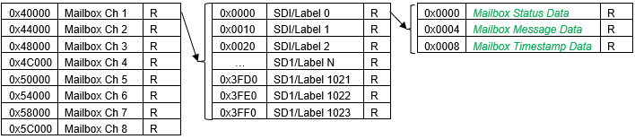
| TIMESTAMP REGISTERS | |||||
| NOTE: Base Address - 0x4010 0000 | |||||
| OFFSET | REGISTER NAME | ACCESS | OFFSET | REGISTER NAME | ACCESS |
| 0x100C | Timestamp Control | R/W | 0x1010 | Timestamp Value | R |
| MESSAGE VALIDATION REGISTERS |
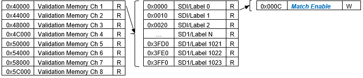
| TRANSMIT FIFO REGISTERS | |||||
| NOTE: Base Address - 0x4010 0000 | |||||
| OFFSET | REGISTER NAME | ACCESS | OFFSET | REGISTER NAME | ACCESS |
| 0x1100 | Transmit FIFO Message Buffer Ch 1 | W | 0x1114 | Transmit FIFO Message Count Ch 1 | R |
| 0x1200 | Transmit FIFO Message Buffer Ch 2 | W | 0x1214 | Transmit FIFO Message Count Ch 2 | R |
| 0x1300 | Transmit FIFO Message Buffer Ch 3 | W | 0x1314 | Transmit FIFO Message Count Ch 3 | R |
| 0x1400 | Transmit FIFO Message Buffer Ch 4 | W | 0x1414 | Transmit FIFO Message Count Ch 4 | R |
| 0x1500 | Transmit FIFO Message Buffer Ch 5 | W | 0x1514 | Transmit FIFO Message Count Ch 5 | R |
| 0x1600 | Transmit FIFO Message Buffer Ch 6 | W | 0x1614 | Transmit FIFO Message Count Ch 6 | R |
| 0x1700 | Transmit FIFO Message Buffer Ch 7 | W | 0x1714 | Transmit FIFO Message Count Ch 7 | R |
| 0x1800 | Transmit FIFO Message Buffer Ch 8 | W | 0x1814 | Transmit FIFO Message Count Ch 8 | R |
| 0x110C | Transmit FIFO Almost Empty Threshold Ch 1 | R/W | 0x111C | Transmit FIFO Rate Ch 1 | R/W |
| 0x120C | Transmit FIFO Almost Empty Threshold Ch 2 | R/W | 0x121C | Transmit FIFO Rate Ch 2 | R/W |
| 0x130C | Transmit FIFO Almost Empty Threshold Ch 3 | R/W | 0x131C | Transmit FIFO Rate Ch 3 | R/W |
| 0x140C | Transmit FIFO Almost Empty Threshold Ch 4 | R/W | 0x141C | Transmit FIFO Rate Ch 4 | R/W |
| 0x150C | Transmit FIFO Almost Empty Threshold Ch 5 | R/W | 0x151C | Transmit FIFO Rate Ch 5 | R/W |
| 0x160C | Transmit FIFO Almost Empty Threshold Ch 6 | R/W | 0x161C | Transmit FIFO Rate Ch 6 | R/W |
| 0x170C | Transmit FIFO Almost Empty Threshold Ch 7 | R/W | 0x171C | Transmit FIFO Rate Ch 7 | R/W |
| 0x180C | Transmit FIFO Almost Empty Threshold Ch 8 | R/W | 0x181C | Transmit FIFO Rate Ch 8 | R/W |
| TRANSMIT SCHEDULING REGISTERS | |||||
| NOTE: Base Address - 0x4010 0000 |
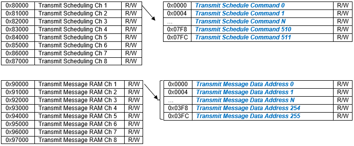
| OFFSET | REGISTER NAME | ACCESS | OFFSET | REGISTER NAME | ACCESS |
| 0x1120 | Async Transmit Data Ch 1 | R/W | |||
| 0x1220 | Async Transmit Data Ch 2 | R/W | |||
| 0x1320 | Async Transmit Data Ch 3 | R/W | |||
| 0x1420 | Async Transmit Data Ch 4 | R/W | |||
| 0x1520 | Async Transmit Data Ch 5 | R/W | |||
| 0x1620 | Async Transmit Data Ch 6 | R/W | |||
| 0x1720 | Async Transmit Data Ch 7 | R/W | |||
| 0x1820 | Async Transmit Data Ch 8 | R/W | |||
| TRANSMIT CONTROL REGISTERS | |||||
| NOTE: Base Address - 0x4010 0000 | |||||
| OFFSET | REGISTER NAME | ACCESS | OFFSET | REGISTER NAME | ACCESS |
| 0x1000 | Tx Trigger | R/W | 0x1004 | Tx Pause | R/W |
| 0x1008 | Tx Stop | R/W | |||
| CONTROL REGISTERS | |||||
| NOTE: Base Address - 0x4010 0000 | |||||
| OFFSET | REGISTER NAME | ACCESS | OFFSET | REGISTER NAME | ACCESS |
| 0x1118 | Channel Control Ch 1 | R/W | 0x1014 | Module Reset | W |
| 0x1218 | Channel Control Ch 2 | R/W | |||
| 0x1318 | Channel Control Ch 3 | R/W | |||
| 0x1418 | Channel Control Ch 4 | R/W | |||
| 0x1518 | Channel Control Ch 5 | R/W | |||
| 0x1618 | Channel Control Ch 6 | R/W | |||
| 0x1718 | Channel Control Ch 7 | R/W | |||
| 0x1818 | Channel Control Ch 8 | R/W | |||
| BIT REGISTERS | |||||
| *When an event is detected, the bit associated with the event is set in this register and will remain set until the user clears the event bit. Clearing the bit requires writing a '1' back to the specific bit that was set when read (i.e., write-1-to-clear, writing a “1” to a bit set to “1” will set the bit to “0). | |||||
| NOTE: Base Address - 0x4000 0000 | |||||
| NOTE: The BIT, channel status and summary status registers are a single block shared by both functions and are located in the Serial (SC3) function's address space at base '0x4000 0000', not in the ARINC function's '0x4010 0000' space. | |||||
| OFFSET | REGISTER NAME | ACCESS | OFFSET | REGISTER NAME | ACCESS |
| 0x0800 | Dynamic Status | R | |||
| 0x0804 | Latched Status* | R/W | |||
| 0x0808 | Interrupt Enable | R/W | |||
| 0x080C | Set Edge/Level Interrupt | R/W | |||
| NOTE: Base Address - 0x4000 0000 | |||||
| 0x0248 | Test Enabled | R/W | 0x02AC | Power-on BIT Complete++ | R |
| 0x02B8 | Background BIT Threshold | R/W | 0x02BC | BIT Count Clear | W |
| ++After power-on, Power-on BIT Complete should be checked before reading the BIT Latched Status. | |||||
| CHANNEL STATUS REGISTERS | |||||
| NOTE: Base Address - 0x4010 0000 | |||||
| OFFSET | REGISTER NAME | ACCESS | OFFSET | REGISTER NAME | ACCESS |
| 0x02B0 | Channel Status Enable | R/W | |||
| *When an event is detected, the bit associated with the event is set in this register and will remain set until the user clears the event bit. Clearing the bit requires writing a '1' back to the specific bit that was set when read (i.e., write-1-to-clear, writing a “1” to a bit set to “1” will set the bit to “0). | |||||
| NOTE: Base Address - 0x4000 0000 | |||||
| NOTE: The BIT, channel status and summary status registers are a single block shared by both functions and are located in the Serial (SC3) function's address space at base '0x4000 0000', not in the ARINC function's '0x4010 0000' space. | |||||
| OFFSET | REGISTER NAME | ACCESS | OFFSET | REGISTER NAME | ACCESS |
| 0x0850 | Dynamic Status Ch 1 | R | 0x0860 | Dynamic Status Ch 2 | R |
| 0x0854 | Latched Status Ch 1* | R/W | 0x0864 | Latched Status Ch 2* | R/W |
| 0x0858 | Interrupt Enable Ch 1 | R/W | 0x0868 | Interrupt Enable Ch 2 | R/W |
| 0x085C | Set Edge/Level Interrupt Ch 1 | R/W | 0x086C | Set Edge/Level Interrupt Ch 2 | R/W |
| 0x0870 | Dynamic Status Ch 3 | R | 0x0880 | Dynamic Status Ch 4 | R |
| 0x0874 | Latched Status Ch 3* | R/W | 0x0884 | Latched Status Ch 4* | R/W |
| 0x0878 | Interrupt Enable Ch 3 | R/W | 0x0888 | Interrupt Enable Ch 4 | R/W |
| 0x087C | Set Edge/Level Interrupt Ch 3 | R/W | 0x088C | Set Edge/Level Interrupt Ch 4 | R/W |
| 0x0890 | Dynamic Status Ch 5 | R | 0x08A0 | Dynamic Status Ch 6 | R |
| 0x0894 | Latched Status Ch 5* | R/W | 0x08A4 | Latched Status Ch 6* | R/W |
| 0x0898 | Interrupt Enable Ch 5 | R/W | 0x08A8 | Interrupt Enable Ch 6 | R/W |
| 0x089C | Set Edge/Level Interrupt Ch 5 | R/W | 0x08AC | Set Edge/Level Interrupt Ch 6 | R/W |
| 0x08B0 | Dynamic Status Ch 7 | R | 0x08C0 | Dynamic Status Ch 8 | R |
| 0x08B4 | Latched Status Ch 7* | R/W | 0x08C4 | Latched Status Ch 8* | R/W |
| 0x08B8 | Interrupt Enable Ch 7 | R/W | 0x08C8 | Interrupt Enable Ch 8 | R/W |
| 0x08BC | Set Edge/Level Interrupt Ch 7 | R/W | 0x08CC | Set Edge/Level Interrupt Ch 8 | R/W |
| SUMMARY STATUS REGISTERS | |||||
| *When an event is detected, the bit associated with the event is set in this register and will remain set until the user clears the event bit. Clearing the bit requires writing a 1 back to the specific bit that was set when read (i.e., write-1-to-clear, writing a “1” to a bit set to “1” will set the bit to “0). | |||||
| NOTE: Base Address - 0x4000 0000 | |||||
| NOTE: The BIT, channel status and summary status registers are a single block shared by both functions and are located in the Serial (SC3) function's address space at base '0x4000 0000', not in the ARINC function's '0x4010 0000' space. | |||||
| OFFSET | REGISTER NAME | ACCESS | OFFSET | REGISTER NAME | ACCESS |
| 0x09A0 | Dynamic Status | R | |||
| 0x09A4 | Latched Status* | R/W | |||
| 0x09A8 | Interrupt Enable | R/W | |||
| 0x09AC | Set Edge/Level Interrupt | R/W | |||
| WDT & INTER-FPGA FAILURE STATUS REGISTERS | |||||
| *When an event is detected, the bit associated with the event is set in this register and will remain set until the user clears the event bit. Clearing the bit requires writing a 1 back to the specific bit that was set when read (i.e., write-1-to-clear, writing a “1” to a bit set to “1” will set the bit to “0). | |||||
| NOTE: Base Address - 0x4000 0000 | |||||
| OFFSET | REGISTER NAME | ACCESS | OFFSET | REGISTER NAME | ACCESS |
| 0x09B0 | Dynamic Status | R | |||
| 0x09B4 | Latched Status* | R/W | |||
| 0x09B8 | Interrupt Enable | R/W | |||
| 0x09BC | Set Edge/Level Interrupt | R/W | |||
| INTERRUPT REGISTERS | |||||
| The Interrupt Vector and Interrupt Steering registers are located on the Motherboard Memory Space and do not require any Module Address Offsets. These registers are accessed using the absolute addresses listed in the table below. NOTE: Vector/Steering 2-5 are allocated for the Serial (SC3) function; vector/steering 6-13 are allocated for the ARINC 429/575 (AR1) function. | |||||
| OFFSET | REGISTER NAME | ACCESS | OFFSET | REGISTER NAME | ACCESS |
| 0x0500 | Module 1 Interrupt Vector 1 - BIT | R/W | 0x0600 | Module 1 Interrupt Steering 1 - BIT | R/W |
| 0x0504 | Module 1 Interrupt Vector 2 - Serial Channel Status Ch 1 | R/W | 0x0604 | Module 1 Interrupt Steering 2 - Serial Channel Status Ch 1 | R/W |
| 0x0508 | Module 1 Interrupt Vector 3 - Serial Channel Status Ch 2 | R/W | 0x0608 | Module 1 Interrupt Steering 3 - Serial Channel Status Ch 2 | R/W |
| 0x050C | Module 1 Interrupt Vector 4 - Serial Channel Status Ch 3 | R/W | 0x060C | Module 1 Interrupt Steering 4 - Serial Channel Status Ch 3 | R/W |
| 0x0510 | Module 1 Interrupt Vector 5 - Serial Channel Status Ch 4 | R/W | 0x0610 | Module 1 Interrupt Steering 5 - Serial Channel Status Ch 4 | R/W |
| 0x0514 | Module 1 Interrupt Vector 6 - AR1 Channel Status Ch 1 | R/W | 0x0614 | Module 1 Interrupt Steering 6 - AR1 Channel Status Ch 1 | R/W |
| 0x0518 | Module 1 Interrupt Vector 7 - AR1 Channel Status Ch 2 | R/W | 0x0618 | Module 1 Interrupt Steering 7 - AR1 Channel Status Ch 2 | R/W |
| 0x051C | Module 1 Interrupt Vector 8 - AR1 Channel Status Ch 3 | R/W | 0x061C | Module 1 Interrupt Steering 8 - AR1 Channel Status Ch 3 | R/W |
| 0x0520 | Module 1 Interrupt Vector 9 - AR1 Channel Status Ch 4 | R/W | 0x0620 | Module 1 Interrupt Steering 9 - AR1 Channel Status Ch 4 | R/W |
| 0x0524 | Module 1 Interrupt Vector 10 - AR1 Channel Status Ch 5 | R/W | 0x0624 | Module 1 Interrupt Steering 10 - AR1 Channel Status Ch 5 | R/W |
| 0x0528 | Module 1 Interrupt Vector 11 - AR1 Channel Status Ch 6 | R/W | 0x0628 | Module 1 Interrupt Steering 11 - AR1 Channel Status Ch 6 | R/W |
| 0x052C | Module 1 Interrupt Vector 12 - AR1 Channel Status Ch 7 | R/W | 0x062C | Module 1 Interrupt Steering 12 - AR1 Channel Status Ch 7 | R/W |
| 0x0530 | Module 1 Interrupt Vector 13 - AR1 Channel Status Ch 8 | R/W | 0x0630 | Module 1 Interrupt Steering 13 - AR1 Channel Status Ch 8 | R/W |
| 0x0534 to 0x0564 | Module 1 Interrupt Vector 14 to 26 - Reserved | R/W | 0x0634 to 0x0664 | Module 1 Interrupt Steering 14 to 26 - Reserved | R/W |
| 0x0568 | Module 1 Interrupt Vector 27 - Summary Status | R/W | 0x0668 | Module 1 Interrupt Steering 27 - Summary Status | R/W |
| 0x056C | Module 1 Interrupt Vector 28 - WDT & Inter-FPGA Failure | R/W | 0x066C | Module 1 Interrupt Steering 28 - WDT & Inter-FPGA Failure | R/W |
| 0x0570 to 0x057C | Module 1 Interrupt Vector 29 to 32 - Reserved | R/W | 0x0670 to 0x067C | Module 1 Interrupt Steering 29 to 32 - Reserved | R/W |
| 0x0700 | Module 2 Interrupt Vector 1 - BIT | R/W | 0x0800 | Module 2 Interrupt Steering 1 - BIT | R/W |
| 0x0704 | Module 2 Interrupt Vector 2 - Serial Channel Status Ch 1 | R/W | 0x0804 | Module 2 Interrupt Steering 2 - Serial Channel Status Ch 1 | R/W |
| 0x0708 | Module 2 Interrupt Vector 3 - Serial Channel Status Ch 2 | R/W | 0x0808 | Module 2 Interrupt Steering 3 - Serial Channel Status Ch 2 | R/W |
| 0x070C | Module 2 Interrupt Vector 4 - Serial Channel Status Ch 3 | R/W | 0x080C | Module 2 Interrupt Steering 4 - Serial Channel Status Ch 3 | R/W |
| 0x0710 | Module 2 Interrupt Vector 5 - Serial Channel Status Ch 4 | R/W | 0x0810 | Module 2 Interrupt Steering 5 - Serial Channel Status Ch 4 | R/W |
| 0x0714 | Module 2 Interrupt Vector 6 - AR1 Channel Status Ch 1 | R/W | 0x0814 | Module 2 Interrupt Steering 6 - AR1 Channel Status Ch 1 | R/W |
| 0x0718 | Module 2 Interrupt Vector 7 - AR1 Channel Status Ch 2 | R/W | 0x0818 | Module 2 Interrupt Steering 7 - AR1 Channel Status Ch 2 | R/W |
| 0x071C | Module 2 Interrupt Vector 8 - AR1 Channel Status Ch 3 | R/W | 0x081C | Module 2 Interrupt Steering 8 - AR1 Channel Status Ch 3 | R/W |
| 0x0720 | Module 2 Interrupt Vector 9 - AR1 Channel Status Ch 4 | R/W | 0x0820 | Module 2 Interrupt Steering 9 - AR1 Channel Status Ch 4 | R/W |
| 0x0724 | Module 2 Interrupt Vector 10 - AR1 Channel Status Ch 5 | R/W | 0x0824 | Module 2 Interrupt Steering 10 - AR1 Channel Status Ch 5 | R/W |
| 0x0728 | Module 2 Interrupt Vector 11 - AR1 Channel Status Ch 6 | R/W | 0x0828 | Module 2 Interrupt Steering 11 - AR1 Channel Status Ch 6 | R/W |
| 0x072C | Module 2 Interrupt Vector 12 - AR1 Channel Status Ch 7 | R/W | 0x082C | Module 2 Interrupt Steering 12 - AR1 Channel Status Ch 7 | R/W |
| 0x0730 | Module 2 Interrupt Vector 13 - AR1 Channel Status Ch 8 | R/W | 0x0830 | Module 2 Interrupt Steering 13 - AR1 Channel Status Ch 8 | R/W |
| 0x0734 to 0x0764 | Module 2 Interrupt Vector 14 to 26 - Reserved | R/W | 0x0834 to 0x0864 | Module 2 Interrupt Steering 14 to 26 - Reserved | R/W |
| 0x0768 | Module 2 Interrupt Vector 27 - Summary Status | R/W | 0x0868 | Module 2 Interrupt Steering 27 - Summary Status | R/W |
| 0x076C | Module 2 Interrupt Vector 28 - WDT & Inter-FPGA Failure | R/W | 0x086C | Module 2 Interrupt Steering 28 - WDT & Inter-FPGA Failure | R/W |
| 0x0770 to 0x077C | Module 2 Interrupt Vector 29 to 32 - Reserved | R/W | 0x0870 to 0x087C | Module 2 Interrupt Steering 29 to 32 - Reserved | R/W |
| 0x0900 | Module 3 Interrupt Vector 1 - BIT | R/W | 0x0A00 | Module 3 Interrupt Steering 1 - BIT | R/W |
| 0x0904 | Module 3 Interrupt Vector 2 - Serial Channel Status Ch 1 | R/W | 0x0A04 | Module 3 Interrupt Steering 2 - Serial Channel Status Ch 1 | R/W |
| 0x0908 | Module 3 Interrupt Vector 3 - Serial Channel Status Ch 2 | R/W | 0x0A08 | Module 3 Interrupt Steering 3 - Serial Channel Status Ch 2 | R/W |
| 0x090C | Module 3 Interrupt Vector 4 - Serial Channel Status Ch 3 | R/W | 0x0A0C | Module 3 Interrupt Steering 4 - Serial Channel Status Ch 3 | R/W |
| 0x0910 | Module 3 Interrupt Vector 5 - Serial Channel Status Ch 4 | R/W | 0x0A10 | Module 3 Interrupt Steering 5 - Serial Channel Status Ch 4 | R/W |
| 0x0914 | Module 3 Interrupt Vector 6 - AR1 Channel Status Ch 1 | R/W | 0x0A14 | Module 3 Interrupt Steering 6 - AR1 Channel Status Ch 1 | R/W |
| 0x0918 | Module 3 Interrupt Vector 7 - AR1 Channel Status Ch 2 | R/W | 0x0A18 | Module 3 Interrupt Steering 7 - AR1 Channel Status Ch 2 | R/W |
| 0x091C | Module 3 Interrupt Vector 8 - AR1 Channel Status Ch 3 | R/W | 0x0A1C | Module 3 Interrupt Steering 8 - AR1 Channel Status Ch 3 | R/W |
| 0x0920 | Module 3 Interrupt Vector 9 - AR1 Channel Status Ch 4 | R/W | 0x0A20 | Module 3 Interrupt Steering 9 - AR1 Channel Status Ch 4 | R/W |
| 0x0924 | Module 3 Interrupt Vector 10 - AR1 Channel Status Ch 5 | R/W | 0x0A24 | Module 3 Interrupt Steering 10 - AR1 Channel Status Ch 5 | R/W |
| 0x0928 | Module 3 Interrupt Vector 11 - AR1 Channel Status Ch 6 | R/W | 0x0A28 | Module 3 Interrupt Steering 11 - AR1 Channel Status Ch 6 | R/W |
| 0x092C | Module 3 Interrupt Vector 12 - AR1 Channel Status Ch 7 | R/W | 0x0A2C | Module 3 Interrupt Steering 12 - AR1 Channel Status Ch 7 | R/W |
| 0x0930 | Module 3 Interrupt Vector 13 - AR1 Channel Status Ch 8 | R/W | 0x0A30 | Module 3 Interrupt Steering 13 - AR1 Channel Status Ch 8 | R/W |
| 0x0934 to 0x0964 | Module 3 Interrupt Vector 14 to 26 - Reserved | R/W | 0x0A34 to 0x0A64 | Module 3 Interrupt Steering 14 to 26 - Reserved | R/W |
| 0x0968 | Module 3 Interrupt Vector 27 - Summary Status | R/W | 0x0A68 | Module 3 Interrupt Steering 27 - Summary Status | R/W |
| 0x096C | Module 3 Interrupt Vector 28 - WDT & Inter-FPGA Failure | R/W | 0x0A6C | Module 3 Interrupt Steering 28 - WDT & Inter-FPGA Failure | R/W |
| 0x0970 to 0x097C | Module 3 Interrupt Vector 29 to 32 - Reserved | R/W | 0x0A70 to 0x0A7C | Module 3 Interrupt Steering 29 to 32 - Reserved | R/W |
| 0x0B00 | Module 4 Interrupt Vector 1 - BIT | R/W | 0x0C00 | Module 4 Interrupt Steering 1 - BIT | R/W |
| 0x0B04 | Module 4 Interrupt Vector 2 - Serial Channel Status Ch 1 | R/W | 0x0C04 | Module 4 Interrupt Steering 2 - Serial Channel Status Ch 1 | R/W |
| 0x0B08 | Module 4 Interrupt Vector 3 - Serial Channel Status Ch 2 | R/W | 0x0C08 | Module 4 Interrupt Steering 3 - Serial Channel Status Ch 2 | R/W |
| 0x0B0C | Module 4 Interrupt Vector 4 - Serial Channel Status Ch 3 | R/W | 0x0C0C | Module 4 Interrupt Steering 4 - Serial Channel Status Ch 3 | R/W |
| 0x0B10 | Module 4 Interrupt Vector 5 - Serial Channel Status Ch 4 | R/W | 0x0C10 | Module 4 Interrupt Steering 5 - Serial Channel Status Ch 4 | R/W |
| 0x0B14 | Module 4 Interrupt Vector 6 - AR1 Channel Status Ch 1 | R/W | 0x0C14 | Module 4 Interrupt Steering 6 - AR1 Channel Status Ch 1 | R/W |
| 0x0B18 | Module 4 Interrupt Vector 7 - AR1 Channel Status Ch 2 | R/W | 0x0C18 | Module 4 Interrupt Steering 7 - AR1 Channel Status Ch 2 | R/W |
| 0x0B1C | Module 4 Interrupt Vector 8 - AR1 Channel Status Ch 3 | R/W | 0x0C1C | Module 4 Interrupt Steering 8 - AR1 Channel Status Ch 3 | R/W |
| 0x0B20 | Module 4 Interrupt Vector 9 - AR1 Channel Status Ch 4 | R/W | 0x0C20 | Module 4 Interrupt Steering 9 - AR1 Channel Status Ch 4 | R/W |
| 0x0B24 | Module 4 Interrupt Vector 10 - AR1 Channel Status Ch 5 | R/W | 0x0C24 | Module 4 Interrupt Steering 10 - AR1 Channel Status Ch 5 | R/W |
| 0x0B28 | Module 4 Interrupt Vector 11 - AR1 Channel Status Ch 6 | R/W | 0x0C28 | Module 4 Interrupt Steering 11 - AR1 Channel Status Ch 6 | R/W |
| 0x0B2C | Module 4 Interrupt Vector 12 - AR1 Channel Status Ch 7 | R/W | 0x0C2C | Module 4 Interrupt Steering 12 - AR1 Channel Status Ch 7 | R/W |
| 0x0B30 | Module 4 Interrupt Vector 13 - AR1 Channel Status Ch 8 | R/W | 0x0C30 | Module 4 Interrupt Steering 13 - AR1 Channel Status Ch 8 | R/W |
| 0x0B34 to 0x0B64 | Module 4 Interrupt Vector 14 to 26 - Reserved | R/W | 0x0C34 to 0x0C64 | Module 4 Interrupt Steering 14 to 26 - Reserved | R/W |
| 0x0B68 | Module 4 Interrupt Vector 27 - Summary Status | R/W | 0x0C68 | Module 4 Interrupt Steering 27 - Summary Status | R/W |
| 0x0B6C | Module 4 Interrupt Vector 28 - WDT & Inter-FPGA Failure | R/W | 0x0C6C | Module 4 Interrupt Steering 28 - WDT & Inter-FPGA Failure | R/W |
| 0x0B70 to 0x0B7C | Module 4 Interrupt Vector 29 to 32 - Reserved | R/W | 0x0C70 to 0x0C7C | Module 4 Interrupt Steering 29 to 32 - Reserved | R/W |
| 0x0D00 | Module 5 Interrupt Vector 1 - BIT | R/W | 0x0E00 | Module 5 Interrupt Steering 1 - BIT | R/W |
| 0x0D04 | Module 5 Interrupt Vector 2 - Serial Channel Status Ch 1 | R/W | 0x0E04 | Module 5 Interrupt Steering 2 - Serial Channel Status Ch 1 | R/W |
| 0x0D08 | Module 5 Interrupt Vector 3 - Serial Channel Status Ch 2 | R/W | 0x0E08 | Module 5 Interrupt Steering 3 - Serial Channel Status Ch 2 | R/W |
| 0x0D0C | Module 5 Interrupt Vector 4 - Serial Channel Status Ch 3 | R/W | 0x0E0C | Module 5 Interrupt Steering 4 - Serial Channel Status Ch 3 | R/W |
| 0x0D10 | Module 5 Interrupt Vector 5 - Serial Channel Status Ch 4 | R/W | 0x0E10 | Module 5 Interrupt Steering 5 - Serial Channel Status Ch 4 | R/W |
| 0x0D14 | Module 5 Interrupt Vector 6 - AR1 Channel Status Ch 1 | R/W | 0x0E14 | Module 5 Interrupt Steering 6 - AR1 Channel Status Ch 1 | R/W |
| 0x0D18 | Module 5 Interrupt Vector 7 - AR1 Channel Status Ch 2 | R/W | 0x0E18 | Module 5 Interrupt Steering 7 - AR1 Channel Status Ch 2 | R/W |
| 0x0D1C | Module 5 Interrupt Vector 8 - AR1 Channel Status Ch 3 | R/W | 0x0E1C | Module 5 Interrupt Steering 8 - AR1 Channel Status Ch 3 | R/W |
| 0x0D20 | Module 5 Interrupt Vector 9 - AR1 Channel Status Ch 4 | R/W | 0x0E20 | Module 5 Interrupt Steering 9 - AR1 Channel Status Ch 4 | R/W |
| 0x0D24 | Module 5 Interrupt Vector 10 - AR1 Channel Status Ch 5 | R/W | 0x0E24 | Module 5 Interrupt Steering 10 - AR1 Channel Status Ch 5 | R/W |
| 0x0D28 | Module 5 Interrupt Vector 11 - AR1 Channel Status Ch 6 | R/W | 0x0E28 | Module 5 Interrupt Steering 11 - AR1 Channel Status Ch 6 | R/W |
| 0x0D2C | Module 5 Interrupt Vector 12 - AR1 Channel Status Ch 7 | R/W | 0x0E2C | Module 5 Interrupt Steering 12 - AR1 Channel Status Ch 7 | R/W |
| 0x0D30 | Module 5 Interrupt Vector 13 - AR1 Channel Status Ch 8 | R/W | 0x0E30 | Module 5 Interrupt Steering 13 - AR1 Channel Status Ch 8 | R/W |
| 0x0D34 to 0x0D64 | Module 5 Interrupt Vector 14 to 26 - Reserved | R/W | 0x0E34 to 0x0E64 | Module 5 Interrupt Steering 14 to 26 - Reserved | R/W |
| 0x0D68 | Module 5 Interrupt Vector 27 - Summary Status | R/W | 0x0E68 | Module 5 Interrupt Steering 27 - Summary Status | R/W |
| 0x0D6C | Module 5 Interrupt Vector 28 - WDT & Inter-FPGA Failure | R/W | 0x0E6C | Module 5 Interrupt Steering 28 - WDT & Inter-FPGA Failure | R/W |
| 0x0D70 to 0x0D7C | Module 5 Interrupt Vector 29 to 32 - Reserved | R/W | 0x0E70 to 0x0E7C | Module 5 Interrupt Steering 29 to 32 - Reserved | R/W |
| 0x0F00 | Module 6 Interrupt Vector 1 - BIT | R/W | 0x1000 | Module 6 Interrupt Steering 1 - BIT | R/W |
| 0x0F04 | Module 6 Interrupt Vector 2 - Serial Channel Status Ch 1 | R/W | 0x1004 | Module 6 Interrupt Steering 2 - Serial Channel Status Ch 1 | R/W |
| 0x0F08 | Module 6 Interrupt Vector 3 - Serial Channel Status Ch 2 | R/W | 0x1008 | Module 6 Interrupt Steering 3 - Serial Channel Status Ch 2 | R/W |
| 0x0F0C | Module 6 Interrupt Vector 4 - Serial Channel Status Ch 3 | R/W | 0x100C | Module 6 Interrupt Steering 4 - Serial Channel Status Ch 3 | R/W |
| 0x0F10 | Module 6 Interrupt Vector 5 - Serial Channel Status Ch 4 | R/W | 0x1010 | Module 6 Interrupt Steering 5 - Serial Channel Status Ch 4 | R/W |
| 0x0F14 | Module 6 Interrupt Vector 6 - AR1 Channel Status Ch 1 | R/W | 0x1014 | Module 6 Interrupt Steering 6 - AR1 Channel Status Ch 1 | R/W |
| 0x0F18 | Module 6 Interrupt Vector 7 - AR1 Channel Status Ch 2 | R/W | 0x1018 | Module 6 Interrupt Steering 7 - AR1 Channel Status Ch 2 | R/W |
| 0x0F1C | Module 6 Interrupt Vector 8 - AR1 Channel Status Ch 3 | R/W | 0x101C | Module 6 Interrupt Steering 8 - AR1 Channel Status Ch 3 | R/W |
| 0x0F20 | Module 6 Interrupt Vector 9 - AR1 Channel Status Ch 4 | R/W | 0x1020 | Module 6 Interrupt Steering 9 - AR1 Channel Status Ch 4 | R/W |
| 0x0F24 | Module 6 Interrupt Vector 10 - AR1 Channel Status Ch 5 | R/W | 0x1024 | Module 6 Interrupt Steering 10 - AR1 Channel Status Ch 5 | R/W |
| 0x0F28 | Module 6 Interrupt Vector 11 - AR1 Channel Status Ch 6 | R/W | 0x1028 | Module 6 Interrupt Steering 11 - AR1 Channel Status Ch 6 | R/W |
| 0x0F2C | Module 6 Interrupt Vector 12 - AR1 Channel Status Ch 7 | R/W | 0x102C | Module 6 Interrupt Steering 12 - AR1 Channel Status Ch 7 | R/W |
| 0x0F30 | Module 6 Interrupt Vector 13 - AR1 Channel Status Ch 8 | R/W | 0x1030 | Module 6 Interrupt Steering 13 - AR1 Channel Status Ch 8 | R/W |
| 0x0F34 to 0x0F64 | Module 6 Interrupt Vector 14 to 26 - Reserved | R/W | 0x1034 to 0x1064 | Module 6 Interrupt Steering 14 to 26 - Reserved | R/W |
| 0x0F68 | Module 6 Interrupt Vector 27 - Summary Status | R/W | 0x1068 | Module 6 Interrupt Steering 27 - Summary Status | R/W |
| 0x0F6C | Module 6 Interrupt Vector 28 - WDT & Inter-FPGA Failure | R/W | 0x106C | Module 6 Interrupt Steering 28 - WDT & Inter-FPGA Failure | R/W |
| 0x0F70 to 0x0F7C | Module 6 Interrupt Vector 29 to 32 - Reserved | R/W | 0x1070 to 0x107C | Module 6 Interrupt Steering 29 to 32 - Reserved | R/W |
APPENDIX: PIN-OUT DETAILS
Pin-out details (for reference) are shown below, with respect to DATAIO. Additional information on pin-outs can be found in the Motherboard Operational Manuals.
| Module Signal (Ref Only) | 44-Pin I/O | 50-Pin I/O (Mod Slot 1-J3) | 50-Pin I/O (Mod Slot 2-J4) | 50-Pin I/O (Mod Slot 3-J3) | 50-Pin I/O (Mod Slot 3-J4) | 4 CH Serial & 8 CH ARINC 429/575 (CM9) |
| DATIO1 | 2 | 10 | 1 | 2 | RXDLO-CH1* | |
| DATIO2 | 24 | 35 | 26 | 27 | RXDHI-CH1* | |
| DATIO3 | 3 | 11 | 2 | 3 | TXDLO-CH1* | |
| DATIO4 | 25 | 36 | 27 | 28 | TXDHI-CH1* | |
| DATIO5 | 5 | 13 | 4 | 5 | RXDLO-CH2* | |
| DATIO6 | 27 | 38 | 29 | 30 | RXDHI-CH2* | |
| DATIO7 | 7 | 14 | 5 | 6 | TXDLO-CH2* | |
| DATIO8 | 29 | 39 | 30 | 31 | TXDHI-CH2* | |
| DATIO9 | 8 | 15 | 6 | 7 | RXDLO-CH3* | |
| DATIO10 | 30 | 40 | 31 | 32 | RXDHI-CH3* | |
| DATIO11 | 10 | 17 | 8 | 9 | TXDLO-CH3* | |
| DATIO12 | 32 | 42 | 33 | 34 | TXDHI-CH3* | |
| DATIO13 | 12 | 18 | 9 | 17 | RXDLO-CH4* | |
| DATIO14 | 34 | 43 | 34 | 42 | RXDHI-CH4* | |
| DATIO15 | 13 | 19 | 10 | 18 | TXDLO-CH4* | |
| DATIO16 | 35 | 44 | 35 | 43 | TXDHI-CH4* | |
| DATIO17 | 15 | 21 | 12 | 20 | AR429-A-CH01 | |
| DATIO18 | 37 | 46 | 37 | 45 | AR429-B-CH01 | |
| DATIO19 | 17 | 22 | 13 | 21 | AR429-A-CH02 | |
| DATIO20 | 39 | 47 | 38 | 46 | AR429-B-CH02 | |
| DATIO21 | 18 | 23 | 14 | 22 | AR429-A-CH03 | |
| DATIO22 | 40 | 48 | 39 | 47 | AR429-B-CH03 | |
| DATIO23 | 20 | 25 | 16 | 24 | AR429-A-CH04 | |
| DATIO24 | 42 | 50 | 41 | 49 | AR429-B-CH04 | |
| DATIO25 | 4 | 12 | 3 | 4 | AR429-A-CH05 | |
| DATIO26 | 26 | 37 | 28 | 29 | AR429-B-CH05 | |
| DATIO27 | 9 | 16 | 7 | 8 | AR429-A-CH06 | |
| DATIO28 | 31 | 41 | 32 | 33 | AR429-B-CH06 | |
| DATIO29 | 14 | 20 | 11 | 19 | AR429-B-CH07 | |
| DATIO30 | 36 | 45 | 36 | 44 | AR429-A-CH07 | |
| DATIO31 | 19 | 24 | 15 | 23 | AR429-B-CH08 | |
| DATIO32 | 41 | 49 | 40 | 48 | AR429-A-CH08 | |
| DATIO33 | 6 | |||||
| DATIO34 | 28 | |||||
| DATIO35 | 11 | |||||
| DATIO36 | 33 | |||||
| DATIO37 | 16 | |||||
| DATIO38 | 38 | |||||
| DATIO39 | 21 | |||||
| DATIO40 | 43 | |||||
| N/A |
*Pin signals for SC3 function are dependent on number of channels used and how those channels are programmed. See table below for additional pinout details.
| CM9 (SC3 Function) Pinouts | RS232 Async | RS232 GPIO | RS232 Async w/ HW Flow | RS232 Sync | RS422/485 Async | RS422/485 GPIO | RS422/485 Async w/ HW Flow | RS422/485 Sync |
| RXDLO-CH1 | RXD-CH1 | GPI2-CH1 | RXD-CH1 | RXD-CH1 | RXDLO-CH1 | GPI-LO-CH1 | RXDLO-CH1 | RXDLO-CH1 |
| RXDHI-CH1 | n/a | GPI1-CH1 | n/a | n/a | RXDHI-CH1 | GPI-HI-CH1 | RXDHI-CH1 | RXDHI-CH1 |
| TXDLO-CH1 | TXD-CH1 | GPO2-CH1 | TXD-CH1 | TXD-CH1 | TXDLO-CH1 | GPO-LO-CH1 | TXDLO-CH1 | TXDLO-CH1 |
| TXDHI-CH1 | n/a | GPO1-CH1 | n/a | n/a | TXDHI-CH1 | GPO-HI-CH1 | TXDHI-CH1 | TXDHI-CH1 |
| … | ||||||||
| RXDLO-CH2 | RXD-CH2 | GPI2-CH2 | RXD-CH2 | RXD-CH2 | RXDLO-CH2 | GPI-LO-CH2 | RXDLO-CH2 | RXDLO-CH2 |
| RXDHI-CH2 | n/a | GPI1-CH2 | n/a | n/a | RXDHI-CH2 | GPI-HI-CH2 | RXDHI-CH2 | RXDHI-CH2 |
| TXDLO-CH2 | TXD-CH2 | GPO2-CH2 | TXD-CH2 | TXD-CH2 | TXDLO-CH2 | GPO-LO-CH2 | TXDLO-CH2 | TXDLO-CH2 |
| TXDHI-CH2 | n/a | GPO1-CH2 | n/a | n/a | TXDHI-CH2 | GPO-HI-CH2 | TXDHI-CH2 | TXDHI-CH2 |
| … | ||||||||
| RXDLO-CH3 | RXD-CH3 | GPI2-CH3 | n/a | n/a | RXDLO-CH3 | GPI-LO-CH3 | CTS-LO-CH1 | CLKIN-LO-CH1 |
| RXDHI-CH3 | n/a | GPI1-CH3 | CTS-CH1 | CLKIN-CH1 | RXDHI-CH3 | GPI-HI-CH3 | CTS-HI-CH1 | CLKIN-HI-CH1 |
| TXDLO-CH3 | TXD-CH3 | GPO2-CH3 | n/a | n/a | TXDLO-CH3 | GPO-LO-CH3 | RTS-LO-CH1 | CLKOUT-LO-CH1 |
| TXDHI-CH3 | n/a | GPO1-CH3 | RTS-CH1 | CLKOUTLO-CH1 | TXDHI-CH3 | GPO-HI-CH3 | RTS-HI-CH1 | CLKOUT-HI-CH 1 |
| … | ||||||||
| RXDLO-CH4 | RXD-CH4 | GPI2-CH4 | n/a | n/a | RXDLO - 4 | GPI-LO-CH4 | CTS-LO-CH2 | CLKIN-LO-CH2 |
| RXDHI-CH4 | n/a | GPI1-CH4 | CTS-CH2 | CLKIN-CH2 | RXDHI - 4 | GPI-HI-CH4 | CTS-HI-CH2 | CLKIN-HI-CH 2 |
| TXDLO-CH4 | TXD-CH4 | GPO2-CH4 | n/a | n/a | TXDLO - 4 | GPO-LO-CH4 | RTS-LO-CH2 | CLKOUT-LO-CH2 |
| TXDHI-CH4 | n/a | GPO1-CH4 | RTS- CH2 | CLKOUTLO-CH2 | TXDHI - 4 | GPO-HI-CH4 | RTS-HI-CH2 | CLKOUT-HI-CH2 |
DOCS.NAII REVISIONS
| Revision Date | Description |
| 2026-11-10 | Initial release of CM9 manual. |
STATUS AND INTERRUPTS
Status registers indicate the detection of faults or events. The status registers can be channel bit-mapped or event bit-mapped. An example of a channel bit-mapped register is the BIT status register, and an example of an event bit-mapped register is the FIFO status register.
For those status registers that allow interrupts to be generated upon the detection of the fault or the event, there are four registers associated with each status: Dynamic, Latched, Interrupt Enabled, and Set Edge/Level Interrupt.
Dynamic Status: The Dynamic Status register indicates the current condition of the fault or the event. If the fault or the event is momentary, the contents in this register will be clear when the fault or the event goes away. The Dynamic Status register can be polled, however, if the fault or the event is sporadic, it is possible for the indication of the fault or the event to be missed.
Latched Status: The Latched Status register indicates whether the fault or the event has occurred and keeps the state until it is cleared by the user. Reading the Latched Status register is a better alternative to polling the Dynamic Status register because the contents of this register will not clear until the user commands to clear the specific bit(s) associated with the fault or the event in the Latched Status register. Once the status register has been read, the act of writing a 1 back to the applicable status register to any specific bit (channel/event) location will “clear” the bit (set the bit to 0). When clearing the channel/event bits, it is strongly recommended to write back the same bit pattern as read from the Latched Status register. For example, if the channel bit-mapped Latched Status register contains the value 0x0000 0005, which indicates fault/event detection on channel 1 and 3, write the value 0x0000 0005 to the Latched Status register to clear the fault/event status for channel 1 and 3. Writing a “1” to other channels that are not set (example 0x0000 000F) may result in incorrectly “clearing” incoming faults/events for those channels (example, channel 2 and 4).
Interrupt Enable: If interrupts are preferred upon the detection of a fault or an event, enable the specific channel/event interrupt in the Interrupt Enable register. The bits in Interrupt Enable register map to the same bits in the Latched Status register. When a fault or event occurs, an interrupt will be fired. Subsequent interrupts will not trigger until the application acknowledges the fired interrupt by clearing the associated channel/event bit in the Latched Status register. If the interruptible condition is still persistent after clearing the bit, this may retrigger the interrupt depending on the Edge/Level setting.
Set Edge/Level Interrupt: When interrupts are enabled, the condition on retriggering the interrupt after the Latch Register is “cleared” can be specified as “edge” triggered or “level” triggered. Note, the Edge/Level Trigger also affects how the Latched Register value is adjusted after it is “cleared” (see below).
Edge triggered: An interrupt will be retriggered when the Latched Status register change from low (0) to high (1) state. Uses for edge-triggered interrupts would include transition detections (Low-to-High transitions, High-to-Low transitions) or fault detections. After “clearing” an interrupt, another interrupt will not occur until the next transition or the re-occurrence of the fault again.
Level triggered: An interrupt will be generated when the Latched Status register remains at the high (1) state. Level-triggered interrupts are used to indicate that something needs attention.
Interrupt Vector and Steering
When interrupts are enabled, the interrupt vector associated with the specific interrupt can be programmed with a unique number/identifier defined by the user such that it can be utilized in the Interrupt Service Routine (ISR) to identify the type of interrupt. When an interrupt occurs, the contents of the Interrupt Vector registers is reported as part of the interrupt mechanism. In addition to specifying the interrupt vector, the interrupt can be directed (“steered”) to the native bus or to the application running on the onboard ARM processor.
Interrupt Trigger Types
In most applications, limiting the number of interrupts generated is preferred as interrupts are costly, thus choosing the correct Edge/Level interrupt trigger to use is important.
Example 1: Fault detection
This example illustrates interrupt considerations when detecting a fault like an “open” on a line. When an “open” is detected, the system will receive an interrupt. If the “open” on the line is persistent and the trigger is set to “edge”, upon “clearing” the interrupt, the system will not regenerate another interrupt. If, instead, the trigger is set to “level”, upon “clearing” the interrupt, the system will re-generate another interrupt. Thus, in this case, it will be better to set the trigger type to “edge”.
Example 2: Threshold detection
This example illustrates interrupt considerations when detecting an event like reaching or exceeding the “high watermark” threshold value. In a communication device, when the number of elements received in the FIFO reaches the high-watermark threshold, an interrupt will be generated. Normally, the application would read the count of the number of elements in the FIFO and read this number of elements from the FIFO. After reading the FIFO data, the application would “clear” the interrupt. If the trigger type is set to “edge”, another interrupt will be generated only if the number of elements in FIFO goes below the “high watermark” after the “clearing” the interrupt and then fills up to reach the “high watermark” threshold value. Since receiving communication data is inherently asynchronous, it is possible that data can continue to fill the FIFO as the application is pulling data off the FIFO. If, at the time the interrupt is “cleared”, the number of elements in the FIFO is at or above the “high watermark”, no interrupts will be generated. In this case, it will be better to set the trigger type to “level”, as the purpose here is to make sure that the FIFO is serviced when the number of elements exceeds the high watermark threshold value. Thus, upon “clearing” the interrupt, if the number of elements in the FIFO is at or above the “high watermark” threshold value, another interrupt will be generated indicating that the FIFO needs to be serviced.
Dynamic and Latched Status Registers Examples
The examples in this section illustrate the differences in behavior of the Dynamic Status and Latched Status registers as well as the differences in behavior of Edge/Level Trigger when the Latched Status register is cleared.
Figure 1. Example of Module's Channel-Mapped Dynamic and Latched Status States
No Clearing of
Latched StatusClearing of Latched Status
(Edge-Triggered)Clearing of Latched Status
(Level-Triggered)Time Dynamic Status Latched Status Action Latched Status Action Latched T0 0x0 0x0 Read Latched Register 0x0 Read Latched Register 0x0 T1 0x1 0x1 Read Latched Register 0x1 0x1 T1 0x1 0x1 Write 0x1 to Latched Register Write 0x1 to Latched Register T1 0x1 0x1 0x0 0x1 T2 0x0 0x1 Read Latched Register 0x0 Read Latched Register 0x1 T2 0x0 0x1 Read Latched Register 0x0 Write 0x1 to Latched Register T2 0x0 0x1 Read Latched Register 0x0 0x0 T3 0x2 0x3 Read Latched Register 0x2 Read Latched Register 0x2 T3 0x2 0x3 Write 0x2 to Latched Register Write 0x2 to Latched Register T3 0x2 0x3 0x0 0x2 T4 0x2 0x3 Read Latched Register 0x1 Read Latched Register 0x3 T4 0x2 0x3 Write 0x1 to Latched Register Write 0x3 to Latched Register T4 0x2 0x3 0x0 0x2 T5 0xC 0xF Read Latched Register 0xC Read Latched Register 0xE T5 0xC 0xF Write 0xC to Latched Register Write 0xE to Latched Register T5 0xC 0xF 0x0 0xC T6 0xC 0xF Read Latched Register 0x0 Read Latched 0xC T6 0xC 0xF Read Latched Register 0x0 Write 0xC to Latched Register T6 0xC 0xF Read Latched Register 0x0 0xC T7 0x4 0xF Read Latched Register 0x0 Read Latched Register 0xC T7 0x4 0xF Read Latched Register 0x0 Write 0xC to Latched Register T7 0x4 0xF Read Latched Register 0x0 0x4 T8 0x4 0xF Read Latched Register 0x0 Read Latched Register 0x4 Interrupt Examples
The examples in this section illustrate the interrupt behavior with Edge/Level Trigger.
Figure 2. Illustration of Latched Status State for Module with 4-Channels with Interrupt Enabled
Time Latched Status
(Edge-Triggered -
Clear Multi-Channel)Latched Status
(Edge-Triggered -
Clear Single Channel)Latched Status
(Level-Triggered -
Clear Multi-Channel)Action Latched Action Latched Action Latched T1
(Int 1)Interrupt Generated
Read Latched Registers0x1 Interrupt Generated
Read Latched Registers0x1 Interrupt Generated
Read Latched Registers0x1 T1
(Int 1)Write 0x1 to Latched Register Write 0x1 to Latched Register Write 0x1 to Latched Register T1
(Int 1)0x0 0x0 Interrupt re-triggers
Note, interrupt re-triggers after
each clear until T2.0x1 T3
(Int 2)Interrupt Generated
Read Latched Registers0x2 Interrupt Generated
Read Latched Registers0x2 Interrupt Generated
Read Latched Registers0x2 T3
(Int 2)Write 0x2 to Latched Register Write 0x2 to Latched Register Write 0x2 to Latched Register T3
(Int 2)0x0 0x0 Interrupt re-triggers
Note, interrupt re-triggers after
each clear until T7.0x2 T4
(Int 3)Interrupt Generated
Read Latched Registers0x1 Interrupt Generated
Read Latched Registers0x1 Interrupt Generated
Read Latched Registers0x3 T4
(Int 3)Write 0x1 to Latched Register Write 0x1 to Latched Register Write 0x3 to Latched Register T4
(Int 3)0x0 0x0 Interrupt re-triggers
Note, interrupt re-triggers after
each clear and 0x3 is reported
in Latched Register until T5.0x3 T4
(Int 3)0x0 0x0 Interrupt re-triggers
Note, interrupt re-triggers after
each clear until T7.0x2 T6
(Int 4)Interrupt Generated
Read Latched Registers0xC Interrupt Generated
Read Latched Registers0xC Interrupt Generated
Read Latched Registers0xE T6
(Int 4)Write 0xC to Latched Register Write 0x4 to Latched Register Write 0xE to Latched Register T6
(Int 4)0x0 Interrupt re-triggers
Write 0x8 to Latched Register0x8 Interrupt re-triggers
Note, interrupt re-triggers after
each clear and 0xE is
reported in Latched Register until T7.0xE T6
(Int 4)0x0 0x0 Interrupt re-triggers
Note, interrupt re-triggers after
each clear and 0xC is
reported in Latched Register until T8.0xC T6
(Int 4)0x0 0x0 Interrupt re-triggers
Note, interrupt re-triggers after
each clear and 0x4 is
reported in Latched Register always.0x4 REVISION HISTORY
Motherboard Manual - Status and Interrupts Revision History Revision Revision Date Description C 2021-11-30 C08896; Transition manual to docbuilder format - no technical info change.
DOCS.NAII REVISIONS Revision Date Description 2026-03-02 Formatting updates to document; no technical changes. 2026-05-18 Fixed formatting issues from conversion to new doc site format. 2026-05-19 Fixed minor formatting issue with Interrupt Examples table structure (removed extraneous cell). 2026-07-15 Revised image files for image quality.
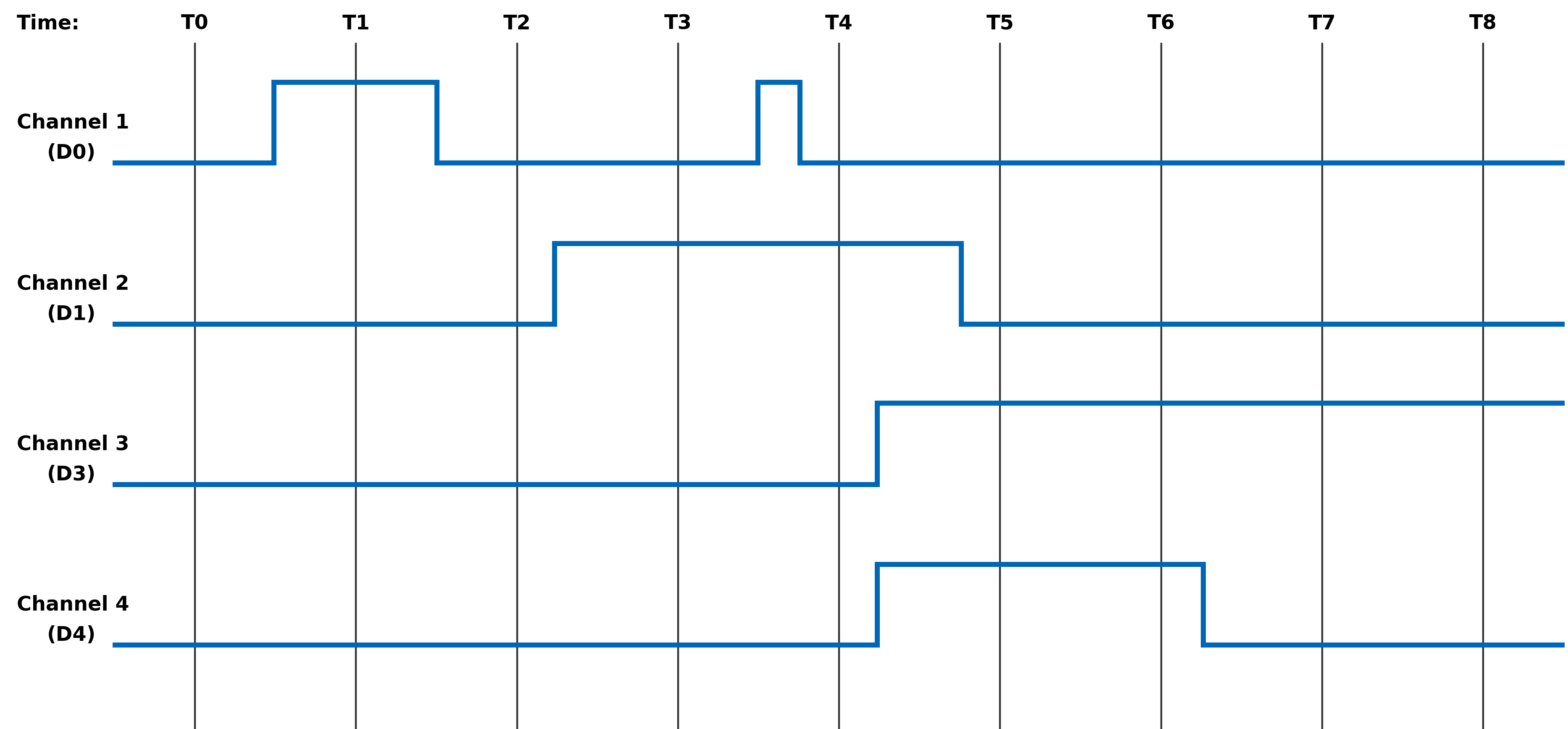
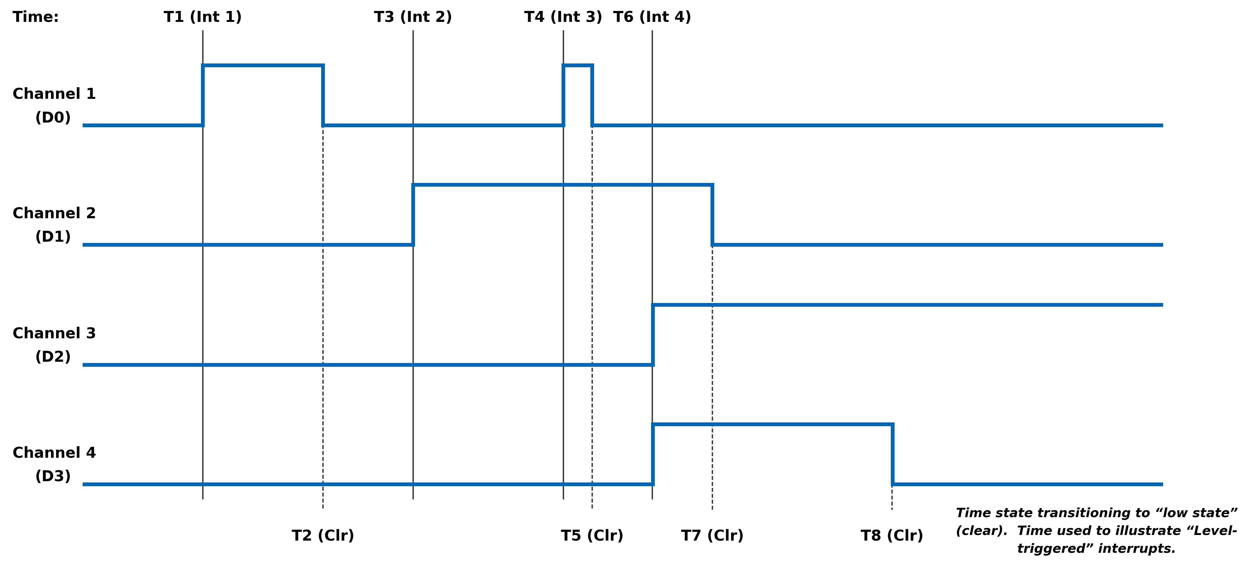
USER WATCHDOG TIMER MODULE MANUAL
User Watchdog Timer Capability
The User Watchdog Timer (UWDT) Capability is available on the following modules:
AC Reference Source Modules
- AC1 - 1 Channel, 2-115 Vrms, 47 Hz - 20kHz
- AC2 - 2 Channels, 2-28 Vrms, 47 Hz - 20kHz
- AC3 - 1 Channel, 28-115 Vrms, 47 Hz - 2.5 kHz
Differential Transceiver Modules
- DF1/DF2 - 16 Channels Differential I/O
Digital-to-Analog (D/A) Modules
- DA1 - 12 Channels, ±10 VDC @ 25 mA, Voltage or Current Control Modes
- DA2 - 16 Channels, ±10 VDC @ 10 mA
- DA3 - 4 Channels, ±40 VDC @ ±100 mA, Voltage or Current Control Modes
- DA4 - 4 Channels, ±80 VDC @ 10 mA
- DA5 - 4 Channels, ±65 VDC or ±2 A, Voltage or Current Control Modes
Digital-to-Synchro/Resolver (D/S) or Digital-to-L( R )VDT (D/LV) Modules
- (Not supported)
Discrete I/O Modules
DT1/DT4 - 24 Channels, Programmable for either input or output, output up to 500 mA per channel from an applied external 3 - 60 VCC source.
DT2/DT5 - 16 Channels, Programmable for either input voltage measurements (±80 V) or as a bi-directional current switch (up to 500 mA per channel).
DT3/DT6 - 4 Channels, Programmable for either input voltage measurements (±100 V) or as a bi-directional current switch (up to 3 A per channel).
TTL/CMOS Modules
- TL1-TL8 - 24 Channels, Programmable for either input or output.
Principle of Operation
The User Watchdog Timer is optionally activated by the applications that require the module’s outputs to be disabled as a failsafe in the event of an application failure or crash. The circuit is designed such that a specific periodic write strobe pattern must be executed by the software to maintain operation and prevent the disablement from taking place.
The User Watchdog Timer is inactive until the application sends an initial strobe by writing the value 0x55AA to the UWDT Strobe register. After activating the User Watchdog Timer, the application must continually strobe the timer within the intervals specified with the configurable UWDT Quiet Time and UWDT Window registers. The timing of the strobes must be consistent with the following rules:
- The application must not strobe during the Quiet time.
- The application must strobe within the Window time.
- The application must not strobe more than once in a single window time.
A violation of any of these rules will trigger a User Watchdog Timer fault and result in shutting down any isolated power supplies and/or disabling any active drive outputs, as applicable for the specific module. Upon a User Watchdog Timer event, recovery to the module shutting down will require the module to be reset.
The Figure 1 and Figure 2 provides an overview and an example with actual values for the User Watchdog Timer Strobes, Quiet Time and Window. As depicted in the diagrams, there are two processes that run in parallel. The Strobe event starts the timer for the beginning of the “Quiet Time”. The timer for the Previous Strobe event continues to run to ensure that no additional Strobes are received within the “Window” associated with the Previous Strobe.
The optimal target for the user watchdog strobes should be at the interval of [Quiet time + ½ Window time] after the previous strobe, which will place the strobe in the center of the window. This affords the greatest margin of safety against unintended disablement in critical operations.
Figure 1. User Watchdog Timer Overview
Figure 2. User Watchdog Timer Example
Figure 3. User Watchdog Timer Failures
Register Descriptions
The register descriptions provide the register name, Type, Data Range, Read or Write information, Initialized Value, and a description of the function.
User Watchdog Timer Registers
The registers associated with the User Watchdog Timer provide the ability to specify the UWDT Quiet Time and the UWDT Window that will be monitored to ensure that EXACTLY ONE User Watchdog Timer (UWDT) Strobe is written within the window.
UWDT Quiet Time Function: Sets Quiet Time value (in microseconds) to use for the User Watchdog Timer Frame. Type: unsigned binary word (32-bit) Data Range: 0 µsec to 2^32 µsec (0x0 to 0xFFFFFFFF) Read/Write: R/W Initialized Value: 0x0 Operational Settings: LSB = 1 µsec. The application must NOT write a strobe in the time between the previous strobe and the end of the Quiet time interval. In addition, the application must write in the UWDT Window EXACTLY ONCE. UWDT Window Function: Writes the window value (in microseconds) to be used for the User Watchdog Timer Frame. Type: unsigned binary word (32-bit) Data Range: 0 µsec to 2^32 µsec (0x0 to 0xFFFFFFFF) Read/Write: R/W Initialized Value: 0x0 Operational Settings: LSB = 1 µsec. The application must write the strobe once within the Window time after the end of the Quiet time interval. The application must write in the UWDT Window EXACTLY ONCE. This setting must be initialized to a non-zero value for operation and should allow sufficient tolerance for strobe timing by the application. UWDT Strobe Function: Writes the strobe value to be use for the User Watchdog Timer Frame. Type: unsigned binary word (32-bit) Data Range: 0x55AA Read/Write: W Initialized Value: 0x0 Operational Settings: At startup, the user watchdog is disabled. Write the value of 0x55AA to this register to start the user watchdog timer monitoring after initial power on or a reset. To prevent a disablement, the application must periodically write the strobe based on the user watchdog timer rules. Status and Interrupt
The modules that are capable of User Watchdog Timer support provide status registers for the User Watchdog Timer.
User Watchdog Timer Status
The status register that contains the User Watchdog Timer Fault information is also used to indicate channel Inter-FPGA failures on modules that have communication between FPGA components. There are four registers associated with the User Watchdog Timer Fault/Inter-FPGA Failure Status: Dynamic, Latched, Interrupt Enable, and Set Edge/Level Interrupt.
Function: Sets the corresponding bit (D31) associated with the channel’s User Watchdog Timer Fault error. Type: unsigned binary word (32-bit) Data Range: 0x0000 0000 to 0xFFFF FFFF Read/Write: R (Dynamic), R/W (Latched, Interrupt Enable, Set Edge/Level Interrupt) Initialized Value: 0
User Watchdog Timer Fault/Inter-FPGA Failure Dynamic Status User Watchdog Timer Fault/Inter-FPGA Failure Latched Status User Watchdog Timer Fault/Inter-FPGA Failure Interrupt Enable User Watchdog Timer Fault/Inter-FPGA Failure Set Edge/Level Interrupt Bit(s) Status Description D31 User Watchdog Timer Fault Status 0 = No Fault + 1 = User Watchdog Timer Fault D30:D0 Reserved for Inter-FPGA Failure Status Channel bit-mapped indicating channel inter FPGA communication failure detection. Interrupt Vector and Steering
When interrupts are enabled, the interrupt vector associated with the specific interrupt can be programmed (typically with a unique number/identifier) such that it can be utilized in the Interrupt Service Routine (ISR) to identify the type of interrupt. When an interrupt occurs, the contents of the Interrupt Vector registers is reported as part of the interrupt mechanism.
In addition to specifying the interrupt vector, the interrupt can be directed (“steered”) to the native bus or to the application running on the onboard ARM processor.
Note
the Interrupt Vector and Interrupt Steering registers are mapped to the Motherboard Common Memory and these registers are associated with the Module Slot position (refer to Function Register Map).
Interrupt Vector Function: Set an identifier for the interrupt. Type: unsigned binary word (32-bit) Data Range: 0 to 0xFFFF FFFF Read/Write: R/W Initialized Value: 0 Operational Settings: When an interrupt occurs, this value is reported as part of the interrupt mechanism. Interrupt Steering Function: Sets where to direct the interrupt. Type: unsigned binary word (32-bit) Data Range: See table Read/Write: R/W Initialized Value: 0 Operational Settings: When an interrupt occurs, the interrupt is sent as specified:
Direct Interrupt to VME 1 Direct Interrupt to ARM Processor (via SerDes)
(Custom App on ARM or NAI Ethernet Listener App)2 Direct Interrupt to PCIe Bus 5 Direct Interrupt to cPCI Bus 6 Function Register Map
KEY
Configuration/Control Measurement/Status
USER WATCHDOG TIMER REGISTERS OFFSET REGISTER NAME ACCESS OFFSET REGISTER NAME ACCESS 0x01C0 UWDT Quiet Time R/W 0x01C4 UWDT Window R/W 0x01C8 UWDT Strobe R/W STATUS REGISTERS *When an event is detected, the bit associated with the event is set in this register and will remain set until the user clears the event bit. Clearing the bit requires writing a 1 back to the specific bit that was set when read (i.e., write-1-to-clear, writing a “1” to a bit set to “1” will set the bit to “0”). OFFSET REGISTER NAME ACCESS OFFSET REGISTER NAME ACCESS 0x09B0 Dynamic Status R 0x09B4 Latched Status* R/W 0x09B8 Interrupt Enable R/W 0x09BC Set Edge/Level Interrupt R/W INTERRUPT REGISTERS The Interrupt Vector and Interrupt Steering registers are mapped to the Motherboard Memory Space and these addresses are absolute based on the module slot position. In other words, do not apply the Module Address offset to these addresses. OFFSET REGISTER NAME ACCESS OFFSET REGISTER NAME ACCESS 0x056C Module 1 Interrupt Vector 28 - User Watchdog Timer Fault/Inter-FPGA Failure R/W 0x066C Module 1 Interrupt Steering 28 - User Watchdog Timer Fault/Inter-FPGA Failure R/W 0x076C Module 2 Interrupt Vector 28 - User Watchdog Timer Fault/Inter-FPGA Failure R/W 0x086C Module 2 Interrupt Steering 28 - User Watchdog Timer Fault/Inter-FPGA Failure R/W 0x096C Module 3 Interrupt Vector 28 - User Watchdog Timer Fault/Inter-FPGA Failure R/W 0x0A6C Module 3 Interrupt Steering 28 - User Watchdog Timer Fault/Inter-FPGA Failure R/W 0x0B6C Module 4 Interrupt Vector 28 - User Watchdog Timer Fault/Inter-FPGA Failure R/W 0x0C6C Module 4 Interrupt Steering 28 - User Watchdog Timer Fault/Inter-FPGA Failure R/W 0x0D6C Module 5 Interrupt Vector 28 - User Watchdog Timer Fault/Inter-FPGA Failure R/W 0x0E6C Module 5 Interrupt Steering 28 - User Watchdog Timer Fault/Inter-FPGA Failure R/W 0x0F6C Module 6 Interrupt Vector 28 - User Watchdog Timer Fault/Inter-FPGA Failure R/W 0x106C Module 6 Interrupt Steering 28 - User Watchdog Timer Fault/Inter-FPGA Failure R/W REVISION HISTORY
Motherboard Manual - Status and Interrupts Revision History Revision Revision Date Description C 2021-11-30 C08896; Transition manual to docbuilder format - no technical info change. DOCS.NAII REVISIONS
Revision Date Description 2026-03-02 Formatting updates to document; no technical changes.
MODULE COMMON REGISTERS
The registers described in this document are common to all NAI Generation 5 modules.
Module Information Registers
The registers in this section provide module information such as firmware revisions, capabilities and unique serial number information.
FPGA Version Registers
The FPGA firmware version registers include registers that contain the Revision, Compile Timestamp, SerDes Revision, Template Revision and Zynq Block Revision information.
FPGA Revision Function: FPGA firmware revision Type: unsigned binary word (32-bit) Data Range: 0x0000 0000 to 0xFFFF FFFF Read/Write: R Initialized Value: Value corresponding to the revision of the board's FPGA Operational Settings: The upper 16-bits are the major revision and the lower 16-bits are the minor revision.
D31 D30 D29 D28 D27 D26 D25 D24 D23 D22 D21 D20 D19 D18 D17 D16 Major Revision Number D15 D14 D13 D12 D11 D10 D9 D8 D7 D6 D5 D4 D3 D2 D1 D0 Minor Revision Number
FPGA Compile Timestamp Function: Compile Timestamp for the FPGA firmware. Type: unsigned binary word (32-bit) Data Range: N/A Read/Write: R Initialized Value: Value corresponding to the compile timestamp of the board's FPGA Operational Settings: The 32-bit value represents the Day, Month, Year, Hour, Minutes and Seconds as formatted in the table:
D31 D30 D29 D28 D27 D26 D25 D24 D23 D22 D21 D20 D19 D18 D17 D16 day (5-bits) month (4-bits) year (6-bits) hr D15 D14 D13 D12 D11 D10 D9 D8 D7 D6 D5 D4 D3 D2 D1 D0 hour (5-bits) minutes (6-bits) seconds (6-bits)
FPGA SerDes Revision Function: FPGA SerDes revision Type: unsigned binary word (32-bit) Data Range: 0x0000 0000 to 0xFFFF FFFF Read/Write: R Initialized Value: Value corresponding to the SerDes revision of the board's FPGA Operational Settings: The upper 16-bits are the major revision, and the lower 16-bits are the minor revision.
D31 D30 D29 D28 D27 D26 D25 D24 D23 D22 D21 D20 D19 D18 D17 D16 Major Revision Number D15 D14 D13 D12 D11 D10 D9 D8 D7 D6 D5 D4 D3 D2 D1 D0 Minor Revision Number
FPGA Template Revision Function: FPGA Template revision Type: unsigned binary word (32-bit) Data Range: 0x0000 0000 to 0xFFFF FFFF Read/Write: R Initialized Value: Value corresponding to the template revision of the board's FPGA Operational Settings: The upper 16-bits are the major revision, and the lower 16-bits are the minor revision.
D31 D30 D29 D28 D27 D26 D25 D24 D23 D22 D21 D20 D19 D18 D17 D16 Major Revision Number D15 D14 D13 D12 D11 D10 D9 D8 D7 D6 D5 D4 D3 D2 D1 D0 Minor Revision Number
FPGA Zynq Block Revision Function: FPGA Zynq Block revision Type: unsigned binary word (32-bit) Data Range: 0x0000 0000 to 0xFFFF FFFF Read/Write: R Initialized Value: Value corresponding to the Zynq block revision of the board's FPGA Operational Settings: The upper 16-bits are the major revision, and the lower 16-bits are the minor revision.
D31 D30 D29 D28 D27 D26 D25 D24 D23 D22 D21 D20 D19 D18 D17 D16 Major Revision Number D15 D14 D13 D12 D11 D10 D9 D8 D7 D6 D5 D4 D3 D2 D1 D0 Minor Revision Number Bare Metal Version Registers
The Bare Metal firmware version registers include registers that contain the Revision and Compile Time information.
Bare Metal Revision Function: Bare Metal firmware revision Type: unsigned binary word (32-bit) Data Range: 0x0000 0000 to 0xFFFF FFFF Read/Write: R Initialized Value: Value corresponding to the revision of the board's Bare Metal Operational Settings: The upper 16-bits are the major revision and the lower 16-bits are the minor revision.
D31 D30 D29 D28 D27 D26 D25 D24 D23 D22 D21 D20 D19 D18 D17 D16 Major Revision Number D15 D14 D13 D12 D11 D10 D9 D8 D7 D6 D5 D4 D3 D2 D1 D0 Minor Revision Number
Bare Metal Compile Time Function: Provides an ASCII representation of the Date/Time for the Bare Metal compile time. Type: 24-character ASCII string - Six (6) unsigned binary word (32-bit) Data Range: N/A Read/Write: R Initialized Value: Value corresponding to the ASCII representation of the compile time of the board's Bare Metal Operational Settings: The six 32-bit words provide an ASCII representation of the Date/Time. The hexadecimal values in the field below represent: May 17 2019 at 15:38:32 Note
little-endian order of ASCII values
Word 1 (Ex. 0x2079614D) D31 D30 D29 D28 D27 D26 D25 D24 D23 D22 D21 D20 D19 D18 D17 D16 Space (0x20) Month ('y' - 0x79) D15 D14 D13 D12 D11 D10 D9 D8 D7 D6 D5 D4 D3 D2 D1 D0 Month ('a' - 0x61) Month ('M' - 0x4D) Word 2 (Ex. 0x32203731) D31 D30 D29 D28 D27 D26 D25 D24 D23 D22 D21 D20 D19 D18 D17 D16 Year ('2' - 0x32) Space (0x20) D15 D14 D13 D12 D11 D10 D9 D8 D7 D6 D5 D4 D3 D2 D1 D0 Day ('7' - 0x37) Day ('1' - 0x31) Word 3 (Ex. 0x20393130) D31 D30 D29 D28 D27 D26 D25 D24 D23 D22 D21 D20 D19 D18 D17 D16 Space (0x20) Year ('9' - 0x39) D15 D14 D13 D12 D11 D10 D9 D8 D7 D6 D5 D4 D3 D2 D1 D0 Year ('1' - 0x31) Year ('0' - 0x30) Word 4 (Ex. 0x31207461) D31 D30 D29 D28 D27 D26 D25 D24 D23 D22 D21 D20 D19 D18 D17 D16 Hour ('1' - 0x31) Space (0x20) D15 D14 D13 D12 D11 D10 D9 D8 D7 D6 D5 D4 D3 D2 D1 D0 'a' (0x74) 't' (0x61) Word 5 (Ex. 0x38333A35) D31 D30 D29 D28 D27 D26 D25 D24 D23 D22 D21 D20 D19 D18 D17 D16 Minute ('8' - 0x38) Minute ('3' - 0x33) D15 D14 D13 D12 D11 D10 D9 D8 D7 D6 D5 D4 D3 D2 D1 D0 ':' (0x3A) Hour ('5' - 0x35) Word 6 (Ex. 0x0032333A) D31 D30 D29 D28 D27 D26 D25 D24 D23 D22 D21 D20 D19 D18 D17 D16 NULL (0x00) Seconds ('2' - 0x32) D15 D14 D13 D12 D11 D10 D9 D8 D7 D6 D5 D4 D3 D2 D1 D0 Seconds ('3' - 0x33) ':' (0x3A) FSBL Version Registers
The FSBL version registers include registers that contain the Revision and Compile Time information for the First Stage Boot Loader (FSBL).
FSBL Revision Function: FSBL firmware revision Type: unsigned binary word (32-bit) Data Range: 0x0000 0000 to 0xFFFF FFFF Read/Write: R Initialized Value: Value corresponding to the revision of the board's FSBL Operational Settings: The upper 16-bits are the major revision, and the lower 16-bits are the minor revision.
D31 D30 D29 D28 D27 D26 D25 D24 D23 D22 D21 D20 D19 D18 D17 D16 Major Revision Number D15 D14 D13 D12 D11 D10 D9 D8 D7 D6 D5 D4 D3 D2 D1 D0 Minor Revision Number
FSBL Compile Time Function: Provides an ASCII representation of the Date/Time for the FSBL compile time. Type: 24-character ASCII string - Six (6) unsigned binary word (32-bit) Data Range: N/A Read/Write: R Initialized Value: Value corresponding to the ASCII representation of the Compile Time of the board's FSBL Operational Settings: The six 32-bit words provide an ASCII representation of the Date/Time. The hexadecimal values in the field below represent: May 17 2019 at 15:38:32
Note
little-endian order of ASCII values
Word 1 (Ex. 0x2079614D) D31 D30 D29 D28 D27 D26 D25 D24 D23 D22 D21 D20 D19 D18 D17 D16 Space (0x20) Month ('y' - 0x79) D15 D14 D13 D12 D11 D10 D9 D8 D7 D6 D5 D4 D3 D2 D1 D0 Month ('a' - 0x61) Month ('M' - 0x4D) Word 2 (Ex. 0x32203731) D31 D30 D29 D28 D27 D26 D25 D24 D23 D22 D21 D20 D19 D18 D17 D16 Year ('2' - 0x32) Space (0x20) D15 D14 D13 D12 D11 D10 D9 D8 D7 D6 D5 D4 D3 D2 D1 D0 Day ('7' - 0x37) Day ('1' - 0x31) Word 3 (Ex. 0x20393130) D31 D30 D29 D28 D27 D26 D25 D24 D23 D22 D21 D20 D19 D18 D17 D16 Space (0x20) Year ('9' - 0x39) D15 D14 D13 D12 D11 D10 D9 D8 D7 D6 D5 D4 D3 D2 D1 D0 Year ('1' - 0x31) Year ('0' - 0x30) Word 4 (Ex. 0x31207461) D31 D30 D29 D28 D27 D26 D25 D24 D23 D22 D21 D20 D19 D18 D17 D16 Hour ('1' - 0x31) Space (0x20) D15 D14 D13 D12 D11 D10 D9 D8 D7 D6 D5 D4 D3 D2 D1 D0 'a' (0x74) 't' (0x61) Word 5 (Ex. 0x38333A35) D31 D30 D29 D28 D27 D26 D25 D24 D23 D22 D21 D20 D19 D18 D17 D16 Minute ('8' - 0x38) Minute ('3' - 0x33) D15 D14 D13 D12 D11 D10 D9 D8 D7 D6 D5 D4 D3 D2 D1 D0 ':' (0x3A) Hour ('5' - 0x35) Word 6 (Ex. 0x0032333A) D31 D30 D29 D28 D27 D26 D25 D24 D23 D22 D21 D20 D19 D18 D17 D16 NULL (0x00) Seconds ('2' - 0x32) D15 D14 D13 D12 D11 D10 D9 D8 D7 D6 D5 D4 D3 D2 D1 D0 Seconds ('3' - 0x33) ':' (0x3A) Module Serial Number Registers
The Module Serial Number registers include registers that contain the Serial Numbers for the Interface Board and the Functional Board of the module.
Interface Board Serial Number Function: Unique 128-bit identifier used to identify the interface board. Type: 16-character ASCII string - Four (4) unsigned binary words (32-bit) Data Range: N/A Read/Write: R Initialized Value: Serial number of the interface board Operational Settings: This register is for information purposes only.
Functional Board Serial Number Function: Unique 128-bit identifier used to identify the functional board. Type: 16-character ASCII string - Four (4) unsigned binary words (32-bit) Data Range: N/A Read/Write: R Initialized Value: Serial number of the functional board Operational Settings: This register is for information purposes only.
Module Capability Function: Provides indication for whether or not the module can support the following: SerDes block reads, SerDes FIFO block reads, SerDes packing (combining two 16-bit values into one 32-bit value) and floating point representation. The purpose for block access and packing is to improve the performance of accessing larger amounts of data over the SerDes interface. Type: unsigned binary word (32-bit) Data Range: 0x0000 0000 to 0x0000 0107 Read/Write: R Initialized Value: 0x0000 0107 Operational Settings: A “1” in the bit associated with the capability indicates that it is supported.
D31 D30 D29 D28 D27 D26 D25 D24 D23 D22 D21 D20 D19 D18 D17 D16 0 0 0 0 0 0 0 0 0 0 0 0 0 0 0 0 D15 D14 D13 D12 D11 D10 D9 D8 D7 D6 D5 D4 D3 D2 D1 D0 0 0 0 0 0 0 0 Flt-Pt 0 0 0 0 0 Pack FIFO Blk Blk
Module Memory Map Revision Function: Module Memory Map revision Type: unsigned binary word (32-bit) Data Range: 0x0000 0000 to 0xFFFF FFFF Read/Write: R Initialized Value: Value corresponding to the Module Memory Map Revision Operational Settings: The upper 16-bits are the major revision and the lower 16-bits are the minor revision.
D31 D30 D29 D28 D27 D26 D25 D24 D23 D22 D21 D20 D19 D18 D17 D16 Major Revision Number D15 D14 D13 D12 D11 D10 D9 D8 D7 D6 D5 D4 D3 D2 D1 D0 Minor Revision Number Module Measurement Registers
The registers in this section provide module temperature measurement information.
Temperature Readings Registers
The temperature registers provide the current, maximum (from power-up) and minimum (from power-up) Zynq and PCB temperatures.
Interface Board Current Temperature Function: Measured PCB and Zynq Core temperatures on Interface Board. Type: signed byte (8-bits) for PCB and signed byte (8-bits) for Zynq core temperatures Data Range: 0x0000 0000 to 0x0000 FFFF Read/Write: R Initialized Value: Value corresponding to the measured PCB and Zynq core temperatures based on the table below Operational Settings: The upper 16-bits are not used, and the lower 16-bits are the PCB and Zynq Core Temperatures. For example, if the register contains the value 0x0000 202C, this represents PCB Temperature = 32° Celsius and Zynq Temperature = 44° Celsius.
D31 D30 D29 D28 D27 D26 D25 D24 D23 D22 D21 D20 D19 D18 D17 D16 0 0 0 0 0 0 0 0 0 0 0 0 0 0 0 0 D15 D14 D13 D12 D11 D10 D9 D8 D7 D6 D5 D4 D3 D2 D1 D0 PCB Temperature Zynq Core Temperature
Functional Board Current Temperature Function: Measured PCB temperature on Functional Board. Type: signed byte (8-bits) for PCB Data Range: 0x0000 0000 to 0x0000 00FF Read/Write: R Initialized Value: Value corresponding to the measured PCB on the table below Operational Settings: The upper 24-bits are not used, and the lower 8-bits are the PCB Temperature. For example, if the register contains the value 0x0000 0019, this represents PCB Temperature = 25° Celsius.
D31 D30 D29 D28 D27 D26 D25 D24 D23 D22 D21 D20 D19 D18 D17 D16 0 0 0 0 0 0 0 0 0 0 0 0 0 0 0 0 D15 D14 D13 D12 D11 D10 D9 D8 D7 D6 D5 D4 D3 D2 D1 D0 0 0 0 0 0 0 0 0 PCB Temperature
Interface Board Maximum Temperature Function: Maximum PCB and Zynq Core temperatures on Interface Board since power-on. Type: signed byte (8-bits) for PCB and signed byte (8-bits) for Zynq core temperatures Data Range: 0x0000 0000 to 0x0000 FFFF Read/Write: R Initialized Value: Value corresponding to the maximum measured PCB and Zynq core temperatures since power-on based on the table below Operational Settings: The upper 16-bits are not used, and the lower 16-bits are the maximum PCB and Zynq Core Temperatures. For example, if the register contains the value 0x0000 5569, this represents maximum PCB Temperature = 85° Celsius and maximum Zynq Temperature = 105° Celsius.
D31 D30 D29 D28 D27 D26 D25 D24 D23 D22 D21 D20 D19 D18 D17 D16 0 0 0 0 0 0 0 0 0 0 0 0 0 0 0 0 D15 D14 D13 D12 D11 D10 D9 D8 D7 D6 D5 D4 D3 D2 D1 D0 PCB Temperature Zynq Core Temperature
Interface Board Minimum Temperature Function: Minimum PCB and Zynq Core temperatures on Interface Board since power-on. Type: signed byte (8-bits) for PCB and signed byte (8-bits) for Zynq core temperatures Data Range: 0x0000 0000 to 0x0000 FFFF Read/Write: R Initialized Value: Value corresponding to the minimum measured PCB and Zynq core temperatures since power-on based on the table below Operational Settings: The upper 16-bits are not used, and the lower 16-bits are the minimum PCB and Zynq Core Temperatures. For example, if the register contains the value 0x0000 D8E7, this represents minimum PCB Temperature = -40° Celsius and minimum Zynq Temperature = -25° Celsius.
D31 D30 D29 D28 D27 D26 D25 D24 D23 D22 D21 D20 D19 D18 D17 D16 0 0 0 0 0 0 0 0 0 0 0 0 0 0 0 0 D15 D14 D13 D12 D11 D10 D9 D8 D7 D6 D5 D4 D3 D2 D1 D0 PCB Temperature Zynq Core Temperature
Functional Board Maximum Temperature Function: Maximum PCB temperature on Functional Board since power-on. Type: signed byte (8-bits) for PCB Data Range: 0x0000 0000 to 0x0000 00FF Read/Write: R Initialized Value: Value corresponding to the measured PCB on the table below Operational Settings: The upper 24-bits are not used, and the lower 8-bits are the PCB Temperature. For example, if the register contains the value 0x0000 0055, this represents PCB Temperature = 85° Celsius.
D31 D30 D29 D28 D27 D26 D25 D24 D23 D22 D21 D20 D19 D18 D17 D16 0 0 0 0 0 0 0 0 0 0 0 0 0 0 0 0 D15 D14 D13 D12 D11 D10 D9 D8 D7 D6 D5 D4 D3 D2 D1 D0 0 0 0 0 0 0 0 0 PCB Temperature
Functional Board Minimum Temperature Function: Minimum PCB temperature on Functional Board since power-on. Type: signed byte (8-bits) for PCB Data Range: 0x0000 0000 to 0x0000 00FF Read/Write: R Initialized Value: Value corresponding to the measured PCB on the table below Operational Settings: The upper 24-bits are not used, and the lower 8-bits are the PCB Temperature. For example, if the register contains the value 0x0000 00D8, this represents PCB Temperature = -40° Celsius.
D31 D30 D29 D28 D27 D26 D25 D24 D23 D22 D21 D20 D19 D18 D17 D16 0 0 0 0 0 0 0 0 0 0 0 0 0 0 0 0 D15 D14 D13 D12 D11 D10 D9 D8 D7 D6 D5 D4 D3 D2 D1 D0 0 0 0 0 0 0 0 0 PCB Temperature Higher Precision Temperature Readings Registers
These registers provide higher precision readings of the current Zynq and PCB temperatures.
Higher Precision Zynq Core Temperature Function: Higher precision measured Zynq Core temperature on Interface Board. Type: signed word (16-bits) for integer part and unsigned word (16-bits) for fractional part Data Range: 0x0000 0000 to 0xFFFF FFFF Read/Write: R Initialized Value: Measured Zynq Core temperature on Interface Board Operational Settings: The upper 16-bits represent the signed integer part of the temperature and the lower 16-bits represent the fractional part of the temperature with the resolution of 1/1000 of degree Celsius. For example, if the register contains the value 0x002B 0271, this represents Zynq Core Temperature = 43.625° Celsius, and value 0xFFF6 0177 represents -10.375° Celsius.
D31 D30 D29 D28 D27 D26 D25 D24 D23 D22 D21 D20 D19 D18 D17 D16 Signed Integer Part of Temperature D15 D14 D13 D12 D11 D10 D9 D8 D7 D6 D5 D4 D3 D2 D1 D0 Fractional Part of Temperature
Higher Precision Interface PCB Temperature Function: Higher precision measured Interface PCB temperature. Type: signed word (16-bits) for integer part and unsigned word (16-bits) for fractional part Data Range: 0x0000 0000 to 0xFFFF FFFF Read/Write: R Initialized Value: Measured Interface PCB temperature Operational Settings: The upper 16-bits represent the signed integer part of the temperature and the lower 16-bits represent the fractional part of the temperature with the resolution of 1/1000 of degree Celsius. For example, if the register contains the value 0x0020 007D, this represents Interface PCB Temperature = 32.125° Celsius, and value 0xFFE8 036B represents -24.875° Celsius.
D31 D30 D29 D28 D27 D26 D25 D24 D23 D22 D21 D20 D19 D18 D17 D16 Signed Integer Part of Temperature D15 D14 D13 D12 D11 D10 D9 D8 D7 D6 D5 D4 D3 D2 D1 D0 Fractional Part of Temperature
Higher Precision Functional PCB Temperature Function: Higher precision measured Functional PCB temperature. Type: signed word (16-bits) for integer part and unsigned word (16-bits) for fractional part Data Range: 0x0000 0000 to 0xFFFF FFFF Read/Write: R Initialized Value: Measured Functional PCB temperature Operational Settings: The upper 16-bits represent the signed integer part of the temperature and the lower 16-bits represent the fractional part of the temperature with the resolution of 1/100 of degree Celsius. For example, if the register contains the value 0x0018 004B, this represents Functional PCB Temperature = 24.75° Celsius, and value 0xFFD9 0019 represents -39.25° Celsius.
D31 D30 D29 D28 D27 D26 D25 D24 D23 D22 D21 D20 D19 D18 D17 D16 Signed Integer Part of Temperature D15 D14 D13 D12 D11 D10 D9 D8 D7 D6 D5 D4 D3 D2 D1 D0 Fractional Part of Temperature Module Health Monitoring Registers
The registers in this section provide module temperature measurement information. If the temperature measurements reaches the Lower Critical or Upper Critical conditions, the module will automatically reset itself to prevent damage to the hardware.
Module Sensor Summary Status Function: The corresponding sensor bit is set if the sensor has crossed any of its thresholds. Type: unsigned binary word (32-bits) Data Range: See table below Read/Write: R Initialized Value: 0 Operational Settings: This register provides a summary for module sensors. When the corresponding sensor bit is set, the Sensor Threshold Status register for that sensor will indicate the threshold condition that triggered the event.
Bit(s) Sensor D31:D6 Reserved D5 Functional Board PCB Temperature D4 Interface Board PCB Temperature D3:D0 Reserved Module Sensor Registers
The registers listed in this section apply to each module sensor listed for the Module Sensor Summary Status register. Each individual sensor register provides a group of registers for monitoring module temperatures readings. From these registers, a user can read the current temperature of the sensor in addition to the minimum and maximum temperature readings since power-up. Upper and lower critical/warning temperature thresholds can be set and monitored from these registers. When a programmed temperature threshold is crossed, the Sensor Threshold Status register will set the corresponding bit for that threshold. The figure below shows the functionality of this group of registers when accessing the Interface Board PCB Temperature sensor as an example.
Sensor Threshold Status Function: Reflects which threshold has been crossed Type: unsigned binary word (32-bits) Data Range: See table below Read/Write: R Initialized Value: 0 Operational Settings: The associated bit is set when the sensor reading exceed the corresponding threshold settings.
Bit(s) Description D31:D4 Reserved D3 Exceeded Upper Critical Threshold D2 Exceeded Upper Warning Threshold D1 Exceeded Lower Critical Threshold D0 Exceeded Lower Warning Threshold
Sensor Current Reading Function: Reflects current reading of temperature sensor Type: Single Precision Floating Point Value (IEEE-754) Data Range: Single Precision Floating Point Value (IEEE-754) Read/Write: R Initialized Value: N/A Operational Settings: The register represents current sensor reading as a single precision floating point value. For example, for a temperature sensor, register value 0x41C6 0000 represents temperature = 24.75° Celsius.
Sensor Minimum Reading Function: Reflects minimum value of temperature sensor since power up Type: Single Precision Floating Point Value (IEEE-754) Data Range: Single Precision Floating Point Value (IEEE-754) Read/Write: R Initialized Value: N/A Operational Settings: The register represents minimum sensor value as a single precision floating point value. For example, for a temperature sensor, register value 0x41C6 0000 represents temperature = 24.75° Celsius.
Sensor Maximum Reading Function: Reflects maximum value of temperature sensor since power up Type: Single Precision Floating Point Value (IEEE-754) Data Range: Single Precision Floating Point Value (IEEE-754) Read/Write: R Initialized Value: N/A Operational Settings: The register represents maximum sensor value as a single precision floating point value. For example, for a temperature sensor, register value 0x41C6 0000 represents temperature = 24.75° Celsius.
Sensor Lower Warning Threshold Function: Reflects lower warning threshold of temperature sensor Type: Single Precision Floating Point Value (IEEE-754) Data Range: Single Precision Floating Point Value (IEEE-754) Read/Write: R/W Initialized Value: Default lower warning threshold (value dependent on specific sensor) Operational Settings: The register represents sensor lower warning threshold as a single precision floating point value. For example, for a temperature sensor, register value 0xC220 0000 represents temperature = -40.0° Celsius.
Sensor Lower Critical Threshold Function: Reflects lower critical threshold of temperature sensor Type: Single Precision Floating Point Value (IEEE-754) Data Range: Single Precision Floating Point Value (IEEE-754) Read/Write: R/W Initialized Value: Default lower critical threshold (value dependent on specific sensor) Operational Settings: The register represents sensor lower critical threshold as a single precision floating point value. For example, for a temperature sensor, register value 0xC25C 0000 represents temperature = -55.0° Celsius.
Sensor Upper Warning Threshold Function: Reflects upper warning threshold of temperature sensor Type: Single Precision Floating Point Value (IEEE-754) Data Range: Single Precision Floating Point Value (IEEE-754) Read/Write: R/W Initialized Value: Default upper warning threshold (value dependent on specific sensor) Operational Settings: The register represents sensor upper warning threshold as a single precision floating point value. For example, for a temperature sensor, register value 0x42AA 0000 represents temperature = 85.0° Celsius.
Sensor Upper Critical Threshold Function: Reflects upper critical threshold of temperature sensor Type: Single Precision Floating Point Value (IEEE-754) Data Range: Single Precision Floating Point Value (IEEE-754) Read/Write: R/W Initialized Value: Default upper critical threshold (value dependent on specific sensor) Operational Settings: The register represents sensor upper critical threshold as a single precision floating point value. For example, for a temperature sensor, register value 0x42FA 0000 represents temperature = 125.0° Celsius. FUNCTION REGISTER MAP
KEY
Configuration/Control Measurement/Status/Board Information
MODULE INFORMATION REGISTERS OFFSET REGISTER NAME ACCESS OFFSET REGISTER NAME ACCESS 0x003C FPGA Revision R 0x0074 Bare Metal Revision R 0x0030 FPGA Compile Timestamp R 0x0080 Bare Metal Compile Time (Bit 0-31) R 0x0034 FPGA SerDes Revision R 0x0084 Bare Metal Compile Time (Bit 32-63) R 0x0038 FPGA Template Revision R 0x0088 Bare Metal Compile Time (Bit 64-95) R 0x0040 FPGA Zynq Block Revision R 0x008C Bare Metal Compile Time (Bit 96-127) R 0x0090 Bare Metal Compile Time (Bit 128-159) R 0x0094 Bare Metal Compile Time (Bit 160-191) R 0x007C FSBL Revision R 0x00B0 FSBL Compile Time (Bit 0-31) R 0x00B4 FSBL Compile Time (Bit 32-63) R 0x00B8 FSBL Compile Time (Bit 64-95) R 0x00BC FSBL Compile Time (Bit 96-127) R 0x00C0 FSBL Compile Time (Bit 128-159) R 0x00C4 FSBL Compile Time (Bit 160-191) R 0x0000 Interface Board Serial Number (Bit 0-31) R 0x0010 Functional Board Serial Number (Bit 0-31) R 0x0034 Interface Board Serial Number (Bit 32-63) R 0x0014 Functional Board Serial Number (Bit 32-63) R 0x0008 Interface Board Serial Number (Bit 64-95) R 0x0018 Functional Board Serial Number (Bit 64-95) R 0x000C Interface Board Serial Number (Bit 96-127) R 0x001C Functional Board Serial Number (Bit 96-127) R 0x0070 Module Capability R 0x01FC Module Memory Map Revision R
MODULE MEASUREMENTS REGISTERS OFFSET REGISTER NAME ACCESS OFFSET REGISTER NAME ACCESS 0x0200 Interface Board PCB/Zynq Current Temp R 0x0208 Functional Board PCB Current Temp R 0x0218 Interface Board PCB/Zynq Max Temp R 0x0228 Functional Board PCB Max Temp R 0x0220 Interface Board PCB/Zynq Min Temp R 0x0230 Functional Board PCB Min Temp R 0x02C0 Higher Precision Zynq Core Temperature R 0x02C4 Higher Precision Interface PCB Temperature R 0x02E0 Higher Precision Functional PCB Temperature R
MODULE HEALTH MONITORING REGISTERS OFFSET REGISTER NAME ACCESS OFFSET REGISTER NAME ACCESS 0x07F8 Module Sensor Summary Status R
REVISION HISTORY
Motherboard Manual - Module Common Registers Revision History Revision Revision Date Description C 2023-08-11 ECO C10649, initial release of module common registers manual. C1 2024-05-15 ECO C11522, removed Zynq Core/Aux/DDR Voltage register descriptions from Module Measurement Registers. Pg.16, updated Module Sensor Summary Status register to add PS references; updated Bit Table to change voltage/current bits to 'reserved'. Pg.16, updated Module/Power Supply Sensor Registers description to better describe register functionality and to add figure. Pg.17, added 'Exceeded' to threshold bit descriptions. Pg.17-18, removed voltage/current references from sensor descriptions. Pg.20, removed Zynq Core/Aux/DDR Voltage register offsets from Module Measurement Registers. Pg.20, updated Module Health Monitoring Registers offset tables. C2 2024-07-10 ECO C11701, pg.16, updated Module Sensor Summary Status register to remove PS references;updated Bit Table to change PS temperature bits to 'reserved'. Pg.16, updated Module SensorRegisters description to remove PS references. Pg.20, updated Module Health MonitoringRegisters offset tables to remove PS temperature register offsets.
DOCS.NAII REVISIONS Revision Date Description 2025-11-05 Corrected register offsets for Interface Board Min Temp and Function Board Min & Max Temps. 2026-03-02 Formatting updates to document; no technical changes. 2026-05-20 Minor formatting fixes (non-technical changes). 2026-07-15 Updated images for online quality; minor additional formatting updates (no technical changes).


NAI Cares
North Atlantic Industries (NAI) is a leading independent supplier of Embedded I/O Boards, Single Board Computers, Rugged Power Supplies, Embedded Systems and Motion Simulation and Measurement Instruments for the Military, Aerospace and Industrial Industries. We accelerate our clients’ time-to-mission with a unique approach based on a Configurable Open Systems Architecture™ (COSA®) that delivers the best of both worlds: custom solutions from standard COTS components.
We have built a reputation by listening to our customers, understanding their needs, and designing, testing and delivering board and system-level products for their most demanding air, land and sea requirements. If you have any applications or questions regarding the use of our products, please contact us for an expedient solution.
Please visit us at: www.naii.com or select one of the following for immediate assistance:
Documentation
FAQ
Application Notes
http://www.naii.com/applicationnotes
Calibration and Repairs
http://www.naii.com/calibrationrepairs
Call Us
(631) 567-1100