Chassis Management (CH) Family Guide
Overview
The CH family is NAI’s line of Chassis Manager modules. Where every other NAI module is an I/O function you program from the SSK, a Chassis Manager is the opposite: it’s the module that watches over the chassis itself — discovering the cards in the system, monitoring their power, temperature, and health, and powering them up and down on command. Today the family has one member, the CH1.
The CH1 is a VITA 46.11 Tier-2 Chassis Management Controller (ChMC) on a single COSA module. It runs the Chassis Manager service (ChM) under Linux and sits in the middle of a layered management system, talking in two directions:
- Down, over the IPMB — the redundant Intelligent Platform Management Bus (an I²C bus, A/B) on the OpenVPX backplane connects the CH1 to one IPMC (Intelligent Platform Management Controller) per managed card or Field Replaceable Unit (FRU) in the chassis. The CH1 discovers those IPMCs and reads/controls them.
- Up, over Ethernet — the CH1 presents a System Management Interface (SMI) to higher-level System Management Software (SMS) running off-board, using IPMI over the network. Under the SMS’s direction (or its own policies), the CH1 manages the chassis’s power, cooling, and health.
That layering is the thing to hold onto, because the names sound alike. Keeping them straight:
| Term | What it is |
|---|---|
| ChMC | The hardware controller — the management processor on the CH1 module itself. |
| ChM | The Chassis Manager software service running on the ChMC under Linux. It does the discovery, monitoring, and control. |
| IPMC | A per-FRU management controller out in the chassis (one on each managed card). The ChM talks to these over the IPMB. |
| SMS | External System Management Software — the higher-level system, off-board, that the CH1 answers to over Ethernet. |
| FRU | A Field Replaceable Unit — any managed element in the chassis (a card, power supply, fan tray, the chassis itself). |
| IPMB | The redundant I²C management bus on the backplane that wires the ChM to all the IPMCs. |
The CH1 mounts on an NAI COSA motherboard that supports chassis managers (such as the 68G6) inside an SIU system chassis, and can also run as a standalone card in other systems. It comes with discrete control signals for fans, LEDs, and the chassis’s power and reset lines.
Because the CH1 isn’t a function module, you don’t drive it from the naibrd SSK — there’s no naibrd_ch_* API. You interact with it through its consoles and the IPMI/SMI interface instead (see Software). This page is the starting point for the family: understand the role, see the interfaces, wire it in, make first contact, and run your first commands.
Note
Several CH1 capabilities are marked (pending) in the module manual at time of writing — notably the RS-232 serial console, fan/cooling control, and the Platform Event Filter (PEF). They’re described here for completeness and flagged where they appear.
CH1 at a glance
A complete VITA 46.11 chassis-management solution is a stack of controllers. The diagram below shows where the CH1 sits — between the IPMCs that represent each FRU on the redundant IPMB, and the System Management Software that reaches in over the network.
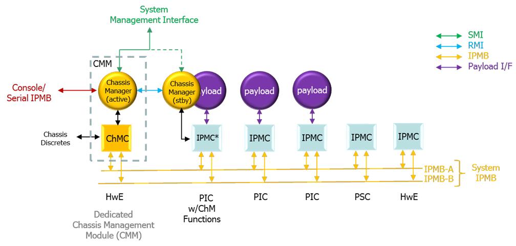
VITA 46.11 chassis management infrastructure
Two physical ports, three software interfaces
The CH1 exposes its function through three software interfaces, reached over two physical connections (Ethernet and a USB-UART hub). Which interface you use depends on whether you’re the production system, a human operator, or a field/debug user:
| Software interface | Reached over | Who uses it | What it’s for |
|---|---|---|---|
| System Management Interface (SMI) | Ethernet (RMCP / IPMI v1.5; REST API for SOSA) | System Management Software, off-board | Production chassis management — the “up to the System Manager” path |
| Operator’s Console | Ethernet, USB-UART (interface 1), or serial console | A human operator | Authenticated terminal: status, FRU discovery, power control, chassis/cache setup, SEL/PEF |
| ChMC Console | USB-UART (interface 2), 115,200 baud | Field / debug | Low-level ChMC CLI — operator / admin / debug command modes (Appendix B of the manual) |
The USB-UART is a quad Silicon Labs CP2108 bridge: interface 1 is the operator’s console, interface 2 is the ChMC console, interface 0 is debug, and interface 3 is unpopulated.
A few more terms you’ll meet
Beyond the ChM/ChMC/IPMC/SMS/FRU/IPMB set above, the rest of this guide uses:
| Term | What it is |
|---|---|
| FRU Inventory | The ChM’s catalog of everything it discovered, each assigned a FRU ID (FRU 0 = the chassis / ChM service at IPMB 20h; FRU 1 = the ChMC at 10h; FRUs up to 252 = the cards; 253 and 254 are reserved logical views of the chassis’s own info — physical and product). |
| SDR Repository | The Sensor Data Records the ChM gathers from every device, telling it (and the SMS) how to interpret each sensor’s readings and events. |
| SEL | The System Event Log — the running log of events the ChM generates or receives. |
| The 8 VITA sensors | Every VITA-compliant FRU (including the ChM and ChMC) carries eight mandatory sensors — FRU state, IPMB link, FRU health/voltage/temperature, payload BIST result/status, and payload mode. |
Form factor and deployment
There’s one CH1 module, but it shows up in a couple of system arrangements worth knowing before you wire it in:
- Form factor — single-wide COSA module for 6U VPX or 3U VPX OpenVPX (VITA 65) chassis.
- Integrated vs standalone — typically integrated on a host MFIO motherboard (e.g. the 68G6) inside an SIU chassis, but it can also run as a standalone card in other systems.
- In-band vs out-of-band management — the 10/100/1000 Base-T port is usually routed outside the chassis to an external LAN for out-of-band management; the 1000 Base-X port lives on the host card and can be routed across the backplane to an on-board SBC for in-band management. Both ports provide the same capabilities.
Standards alignment
The CH1 is built to VITA 46.11-2022 (Tier-2), HOST v3.0, and SOSA v2.0, using IPMI v1.5 and v2.0 as those standards require. (It ships configured for SOSA; contact the factory for other configurations or to align with SOSA REST-API objectives.)
Physical setup
Wiring a CH1 is mostly about connecting to it (so you can manage the chassis) and connecting it into the chassis (so it can manage the FRUs). The first is two ports; the second is a set of control signals brought out during integration.
Connecting to the CH1
Ethernet — two ports, same capability. The module ships pre-configured with a 10/100/1000 Base-T port at 192.168.1.19 and a 1000 Base-X port at 192.168.1.20 (both addresses are user-changeable to fit your network). They differ only in where they route:
- Base-T → out-of-band. Typically routed outside the chassis to an external LAN so off-board System Management Software can reach the CH1 remotely.
- Base-X → in-band. Lives on the 68G6 host card and can be routed across the backplane to an on-board SBC running system management software.
USB-UART hub. A quad Silicon Labs CP2108 USB-to-UART bridge exposes four interfaces; the two that matter are interface 1 (operator’s console) and interface 2 (ChMC console). Interface 0 is debug and interface 3 is unpopulated. The host needs Silicon Labs CP210x VCP drivers (contact the factory if you need help locating them).
Serial console (RS-232) — pending. A future option connects the operator’s console over CHM CONSOLE RX/TX to a terminal program (TeraTerm, PuTTY). The ChMC console expects 115,200 baud, local echo on, 150 ms/line transmit delay, Xon/Xoff flow control.
Power. The CH1 needs 3.3 V_AUX @ 2.0 A. This is usually self-contained and may be gated by a Management Power switch on the chassis.
Connecting the CH1 into the chassis
Beyond the System IPMB (the backplane I²C bus that reaches every IPMC), the CH1 brings out a set of chassis control signals that are wired to the power supply, backplane, and front panel during integration. Which ones are actually connected depends on your chassis — check the chassis wiring diagram against the CH1 pinout, or contact the factory. The main ones:
| Signal | Role |
|---|---|
| ENABLE* | Enables management (3.3 V_AUX) power to the backplane when low. |
| INHIBIT* | Disables payload power rails. The ChM asserts/de-asserts this on power-down/up/cycle commands. |
| FAIL* | A power-supply failure indication, visible to ChM and/or SMS. |
| SYSRESET* | Chassis-wide payload reset (does not affect the ChM or IPMCs). |
| NVMRO | Puts plug-in modules’ non-volatile memory into a write-protected state. |
| gDiscrete1* | User-defined action input, usually a front-panel push-button. |
| Maskable Reset* | ChMC-driven reset to some/all backplane slots. |
| LEDs | Up to three single/multi-color LEDs, controllable from SMS. |
| Fans — pending | Up to two PWM/TACH fan (or fan-group) controls. |
Important
The chassis-control commands later in this guide only do something if the matching signal is physically wired from the CH1 to the power supply / backplane. For example,
payload offonly cuts payload power ifINHIBIT*is connected. An unwired signal makes its command a no-op.
Software
You manage the CH1 through the three interfaces introduced at a glance. Which one you reach for depends on who you are:
-
System Management Interface (SMI) — the production path. Off-board System Management Software opens an authenticated IPMI-over-Ethernet (RMCP) session and issues chassis/FRU commands, reads sensors, and receives forwarded events. For SOSA alignment, the SMI is driven via REST APIs (contact the factory; NAI can include the required software on the chassis manager). The SMI requires login, and each account has a maximum privilege level (user / operator / admin).
-
Operator’s Console — the human interface, and the one this guide’s examples use. It’s a command terminal reached three ways: over Ethernet, over USB-UART interface 1, or (pending) the serial console. From the module’s Linux shell (default login
root, no password), you launch the operator’s console virtual terminal withsudo conspy 10, and can resize it withsudo stty -F /dev/tty10 columns X rows Y. From here you runstatus,get …,payload …, and the setup commands.
Note
The console does not currently enforce authentication — it’s session-less with full (OEM) privilege, so every command is allowed. Don’t treat console access as access-controlled. (The SMI does require login.)
- ChMC Console — the field/debug CLI on USB-UART interface 2, documented in Appendix B of the CH1 Manual. It has three privilege levels: operator (status, FRU identify, limited control), admin (enter with
admin; initial password is NULL, then settable up to 16 chars — view settings, dump/erase SEL & SDR repositories, JTAG MUX, upload config, reboot the ChMC), and debug.
The takeaway: SMS talks to the SMI; you talk to the operator’s console; you reach for the ChMC console when something needs low-level debugging.
Confirm communication
There’s no two-channel loopback here like the I/O modules — the CH1 “self-test” is simply making first contact and confirming the ChM discovered your chassis. Once management power is applied and the ChM service has booted:
- Get on the operator’s console — over USB-UART interface 1, or from the Linux shell with
sudo conspy 10. - Run
status. You should see the chassis identity (name / part # / serial from the product-view FRU info), the current FRU state, and the eight VITA sensors refreshing about once per second. - Run
get frus(andget sites). This lists the FRUs the ChM found on the System IPMB — each with its IPMB status and FRU state. Empty/unmanaged sites show---.
If status reports a sane chassis state and get frus shows the cards you expect with healthy IPMB status, then the module is alive, the ChM service is running, the System IPMB is wired correctly, and discovery worked — the equivalent of a clean self-test.
Note
If the CH1 powers up with no physical Chassis FRU Information, it falls back to an “unknown chassis” data set and scans every possible IPMB address — which makes this first discovery noticeably slow. That’s expected on a bare chassis; see Common pitfalls.
Features
Everything the CH1 does is built on one loop: discover the FRUs, monitor their health, and control their power/state — locally by policy, or on command from an operator or the SMS. The capabilities below are the pieces of that loop. Reach them from the operator’s console (shown in Try it), over the SMI as IPMI commands, or via the ChMC console for debug; the full command and IPMI reference is in the CH1 Manual.
FRU discovery & inventory
At power-up the ChM scans the Chassis Address Table, finds every responding IPMC, and builds a FRU Inventory — assigning each a FRU ID (FRU 0 = the chassis/ChM at 20h, FRU 1 = the ChMC at 10h, cards up to 252; 253/254 are the reserved physical/product chassis views). Discovery is continuous, so a card that’s slow to come up is picked up later by health polling. (See get frus, get sites, get [dev] -i.)
Note
The ChM only manages VITA 46.11-compliant IPMCs whose addresses are in the Chassis Address Table. A Tier-1 IPMC at an address not in the table — or any controller that doesn’t support the VITA command set — won’t be discovered.
Chassis & FRU control
Bring the chassis up and down as a whole (FRU 0) or target individual FRUs. Activation runs startup_script.txt from the ChM cache (or sends FRU-activation commands in order); deactivation runs shutdown_script.txt; power-cycle does both with a configurable delay. Per-FRU you can send cold / warm / graceful resets, and kill immediately asserts INHIBIT* for an emergency shutdown. (See payload on|off|cycle|reset, payload {dev} …, kill.)
Sensors & health monitoring
Every VITA FRU — including the ChM and ChMC — carries the eight mandatory sensors (FRU state, IPMB link state, FRU health / voltage / temperature, payload BIST result / status, payload mode). The chassis-level sensors at 20h are aggregates: a fault on any FRU surfaces on the corresponding chassis sensor, so the chassis FRU_HEALTH is a single pass/fail rollup of the whole system. (Seen in status.)
SDR repository & FRU information
The ChM caches a complete SDR (Sensor Data Record) repository plus FRU information for every device in /etc/ChM, so it (and the SMS) can interpret readings without hitting the IPMB each time. Chassis FRU Information comes in two parallel views: the physical view (FRU 253) — how the backplane vendor built the chassis — and the product view (FRU 254) — how you use it, an overlay you can edit and commit. (See get backplane, get chassis.)
System Event Log & event handling
The ChM keeps a System Event Log (SEL) of events it generates or receives, and points every FRU’s event receiver at itself (20h). By default it is the SEL and logs locally; if the SMS sets a different event-receiver address, the ChM forwards events up over the SMI. Sensor events also feed the chassis aggregate sensors and (when enabled) the cooling control.
Platform Event Filter — pending
The PEF will screen each incoming event against an operator-defined Event Filter Table and trigger actions (resets, power changes, alerts) automatically.
IPMI message bridging
The ChM can bridge a send message command from one interface to another — letting the SMS reach straight through the ChM to a specific FRU’s IPMC over the System IPMB (and, if the IPMC supports it, onward to an IPMI-aware payload). The path works in reverse too.
Cooling management — partly pending
The CH1 has PWM outputs and TACH inputs for up to two fans (or fan groups), controllable two ways that cooperate (actual duty cycle is the higher of the two): local control by the ChMC against a temperature sensor (pending), and ChM control, which implements the VITA 46.11 cooling model — matching fan trays to FRUs via Fan Geography Records and driving fan speed from the hottest associated FRU.
Authentication & privilege
The SMI requires an authenticated session, and each account has a maximum privilege level (user / operator / admin); over-privileged commands are rejected. Notably, a bridged send message inherits the privilege of the message inside it. (As noted above, the console is currently session-less with full privilege.)
Try it
These are real operator’s-console sequences — the CH1 analog of the code snippets in the I/O guides. Get on the console first (sudo conspy 10 from the Linux shell, or USB-UART interface 1), then:
See the chassis and its health
status # chassis identity, FRU state, and the 8 VITA sensors (refreshes ~1/sec)Discover what’s in the chassis
get frus               # summary of every FRU currently under management
get sites              # site population from the Chassis Address Table (empty sites show ---)
get fru 3 -i           # full detail + FRU Information for one FRU (here FRU 3)
Power the payload up and down
payload on             # activate all payload cards (runs startup_script.txt)
payload off            # deactivate all payload cards (runs shutdown_script.txt; asserts INHIBIT*)
payload cycle          # off, wait the configured delay, then on
payload 3 wrst         # warm-reset just FRU 3's payload
Check the management bus and recent events
get ipmb # System IPMB connectivity and capabilities, per FRUFor low-level checks, the ChMC console (USB-UART interface 2) adds debug views like states (live signal/flag states), get ipmb c|p|l (per-bus statistics), and SEL dump N (hex dump of the last N event-log entries). The complete command set for both consoles, and the full IPMI command list, are in the CH1 Manual (Operator’s Console section and Appendices A–B).
Hardware capabilities and status monitoring
This section gathers what the CH1 hardware provides and what you can monitor — for how to drive each capability (discovery, control, event handling), see Features and Try it above.
What the CH1 hardware provides:
- Management processor (ChMC) — the VITA 46.11 Tier-2 controller itself, running the ChM service under Linux; the brain that does discovery, monitoring, and control.
- Redundant System IPMB (A/B) — the backplane I²C management bus that reaches one IPMC per managed FRU.
- Two Ethernet management ports — 10/100/1000 Base-T (out-of-band, off-chassis) and 1000 Base-X (in-band, across the backplane); both provide the same capabilities.
- Quad USB-UART bridge (Silicon Labs CP2108) — carries the operator’s console (interface 1) and the ChMC console (interface 2).
- Chassis control I/O —
ENABLE*,INHIBIT*,FAIL*,SYSRESET*,NVMRO,Maskable Reset*, andgDiscrete1*discretes; up to three SMS-controllable LEDs; and (pending) two PWM/TACH fan channels. Each acts only if physically wired (see Physical setup). - Eight mandatory VITA sensors per FRU, plus chassis-level aggregate sensors at
20hthat roll every FRU’s health into a single system pass/fail. - Cached SDR repository + FRU information in
/etc/ChM, so the ChM (and SMS) can interpret every device’s readings without re-reading the IPMB. - 3.3 V_AUX management power (2.0 A), independent of payload power so the ChM keeps running while the payload is off.
Statuses you can monitor:
| Status | What it tells you | Where |
|---|---|---|
| Chassis health rollup | One pass/fail for the whole system — any FRU fault surfaces here | FRU_HEALTH chassis sensor at 20h, in status |
| The 8 VITA sensors (per FRU) | FRU state, IPMB link, FRU health / voltage / temperature, payload BIST result / status, payload mode | status, get fru N -i |
| FRU inventory & state | What the ChM discovered and each FRU’s current state | get frus, get sites |
| IPMB connectivity | Per-FRU management-bus status and capabilities | get ipmb (per-bus stats via get ipmb c|p|l on the ChMC console) |
| System Event Log (SEL) | Running log of events the ChM generated or received | SEL (SEL dump N on the ChMC console); forwarded to the SMS when an event receiver is set |
| Live signal/flag states | Real-time state of the chassis-control signals and internal flags | states (ChMC console) |
Note
The CH1 has no ESP2 soft panel like the I/O modules — you watch its status live on the operator’s console (
statusrefreshes about once a second) or programmatically over the SMI.
Common pitfalls
- First boot on a bare chassis is slow. With no physical Chassis FRU Information stored, the CH1 defaults to an “unknown chassis” set and scans every IPMB address. Save Chassis FRU Information to the ChM cache (or a backplane storage device) after the first discovery to dramatically cut start-up time.
- A FRU isn’t discovered. Only VITA 46.11-compliant IPMCs at addresses in the Chassis Address Table are managed. A Tier-1 IPMC at an off-table address, or a non-VITA controller, won’t appear. Discovery is also continuous — a slow card may show up a little later.
- A control command does nothing. Chassis-control signals (
INHIBIT*,ENABLE*,SYSRESET*) must be physically wired from the CH1 to the power supply / backplane. If the signal isn’t connected for your chassis, the matching command is a no-op — check the wiring diagram vs the CH1 pinout. - Don’t assume the console is access-controlled. The operator’s console is currently session-less with full OEM privilege, and the default Linux login is
rootwith no password — change this for any deployment. (The SMI does enforce authentication.) - Editing the wrong chassis view. Changes to the physical view (FRU 253) and product view (FRU 254) are separate, and an uncommitted product view gets repopulated from the physical view on the next discovery. Edit and commit the view you mean.
- Pending features. The RS-232 serial console, fan/cooling local control, and the Platform Event Filter are marked pending in the current manual — don’t build a workflow around them without confirming availability with the factory.
Related resources
- CH1 Manual — the full reference: every console command, the Sensor/SDR/FRU model, the supported IPMI command list (Appendix A), and the ChMC CLI (Appendix B).
- VITA 46.11-2022 — the chassis-management standard the CH1 implements (Tier-2), plus HOST v3.0 and SOSA v2.0 alignment.
- IPMI v1.5 / v2.0 — the underlying messaging the SMI and IPMB use.
- The host motherboard manual (e.g. the 68G6) — for how the CH1 is carried, powered, and routed in an integrated system.
- CH1 Integration Guide and ChMgen (ChMCgen) Users Guide — for building Chassis FRU Information, Fan Geography Records, and enabling local fan control (contact the factory).