Summary
The NAI Ethernet Protocol is a binary message framework that lets a host computer talk to an NAI motherboard over TCP or UDP. It runs on top of the NAI Ethernet Listener, a process that runs on the board and accepts incoming requests from the host. Once a connection is open, the host can read or write any motherboard or module register over the network — no shared bus required between host and board.
This page covers the protocol’s concepts and command categories at a high level. For the byte-level command layout, see NAI Ethernet Protocol Reference. For the C API calls that build, send, and decode these messages from your application, see NAI Ethernet Protocol APIs.
When to Use It
The Ethernet Protocol is the right fit when:
- The host computer is on a separate, network-connected machine and can’t share a bus with the board.
- You want to monitor or control a board remotely (for example, from a mission computer or workstation).
- You need to push data, firmware updates, or commands across a network to one or more boards.
- You want unsolicited notifications driven by hardware interrupts or timers (see TDR and IDR commands below).
If your host already shares a PCIe, VME, or local bus with the board, you usually use the standard SSK API directly against that bus instead — it’s lower latency. Many systems mix both: SSK calls locally, plus the Ethernet Protocol for any remote or networked part of the system.
NAI Protocol vs. Raw Sockets
The NAI Ethernet Protocol is a board-control protocol. It exists so you can read and write the board’s registers — and trigger board-level features like TDR, IDR, and Scripts — over the network with structured messages the on-board listener already understands. You don’t have to write any board-side code: the listener is already running.
Raw TCP/UDP sockets (Winsock, BSD sockets, etc.) are a generic transport. They give you a byte stream between two endpoints with no opinion about what those bytes mean. If you want to send arbitrary application data — telemetry payloads, log files, mission-defined messages, a custom protocol of your own — that’s what raw sockets are for.
Use the NAI Ethernet Protocol when you want to:
- Read or write motherboard and module registers from a remote host.
- Have the board push data to you on a timer (TDR) or a hardware interrupt (IDR) — no host-side polling required.
- Store and replay command sequences on the board (Scripts), including a SafeState script that runs on host comm timeout.
- Issue raw I2C transactions from the host side.
- Use the full
naibrd_*and module APIs (e.g.naibrd_AD_*,naibrd_FT_*) transparently over the network, with no changes to the rest of your application code.
Reach for raw sockets (alongside or instead of the NAI protocol) when:
- Your application has its own protocol and the board is just another network endpoint speaking it — code you’ve written that runs on the board reads and writes whatever framing you choose.
- You’re moving large payloads — bulk file transfers, video, audio, telemetry streams — where you control framing for throughput.
- You’re integrating with non-NAI hosts that already have a defined protocol.
- You need a long-lived custom message stream that the NAI Ethernet Listener wouldn’t know what to do with.
A common system pattern uses both: the NAI Ethernet Protocol for board configuration and monitoring (naibrd_* calls over Ethernet), plus raw sockets for moving custom application payloads that your code running on the board produces or consumes.
Note
The NAI Ethernet Listener and any raw socket server you run on the board are independent — they listen on different ports and don’t interfere. The Listener defaults to TCP
52801/ UDP52802; pick your own ports for raw sockets.
Supported Boards
The Ethernet Protocol is supported on current-generation NAI Single Board Computers and Multi-Function I/O motherboards, including:
- Gen 5 — 75G5, 68G5, 64G5, 75ARM1, 75PPC1, 75INT2, 64ARM1, 65PPC1, 64INT2, NIU1A
- Gen 6 — current-generation boards in the same product families
Note
Gen 5 and Gen 6 boards share the same protocol foundation. Gen 6 adds a few additional command variants (for example, extended IDR and block command types). Where they exist, they’re called out in the Reference.
Message Framework
Every command and response uses the same envelope:
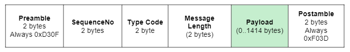
| Field | Description |
|---|---|
| Preamble | Marks the start of a message frame. Always 0xD30F. |
| SequenceNo | Pairs a response with the command that triggered it. The host picks the value for normal commands; the board picks it for unsolicited responses (see TDR/IDR below). |
| TypeCode | Identifies what the message is (ReadRegs, WriteBlock, etc.) and whether it’s a command or a response. |
| Length | Total bytes in the frame, counting Preamble and Postamble. |
| Payload | Command- or response-specific data. |
| Postamble | Marks the end of a message frame. Always 0xF03D. |
Note
All multibyte fields are big-endian.
Command Categories
The categories below describe what each group of commands is for. Byte-level layouts live in the Reference.
Register Commands
The bread-and-butter commands. ReadRegs and WriteRegs operate on one or more registers using a starting address, a count, and a stride. With a stride of zero, the same address is read or written repeatedly — useful for draining a FIFO. With a non-zero stride, the address advances by that many bytes per access, so you can sweep across a contiguous (or strided) range of memory in a single command.
MaskReg and MaskValueReg apply bit-level mask operations to a single register, which is convenient when you only want to flip specific bits without touching the rest of the value.
Block Commands
A Block is a saved list of register addresses on the board. You define a block once with SetBlockConfig, then read or write all of its registers in a single round trip using ReadBlock / WriteBlock. Blocks shine when the registers you care about aren’t contiguous — for example, status registers scattered across several modules.
Block commands: SetBlockConfig, GetBlockConfig, ClearBlockConfig, ReadBlock, WriteBlock.
All registers in a block share the same flags. You can’t mix onboard and off-board addressing in the same block, and you can’t mix 16-bit and 32-bit register sizes.
ZBlock Commands
ZBlocks are the same idea as blocks, but each register address in the list carries its own per-register flags. That means you can mix onboard and off-board addresses in the same ZBlock. The register-size flag still has to be consistent across the block.
ZBlock commands: SetZBlockConfig, GetZBlockConfig, ClearZBlockConfig, ReadZBlock, WriteZBlock.
Timer Driven Response (TDR)
TDRs make the board push data to your host on a fixed timer interval, with no polling required. You define a TDR with SetTDRConfig — giving it a destination IP/port, a period in milliseconds, and a list of register commands to run — then call StartTDR to begin firing. The board executes the commands periodically and sends each response to the address you specified.
Up to 16 TDRs can be defined, each holding up to 4 commands.
TDR commands: SetTDRConfig, GetTDRConfig, ClearTDRConfig, StartTDR, StopTDR.
Interrupt Driven Response (IDR)
IDRs are similar to TDRs but trigger on a hardware interrupt vector instead of a timer. When the configured interrupt fires on the board, the board automatically runs the IDR’s command list and sends the responses back to the host. This is useful for getting status data the instant a meaningful event happens (an end-of-conversion, a fault condition, a comm bus event) instead of polling on a fixed interval.
Up to 16 IDRs can be defined, each holding up to 4 commands.
IDR commands: SetIDRConfig, GetIDRConfig, ClearIDRConfig, EnableIDR, DisableIDR.
Note
For more on motherboard interrupts in general — vectors, steering, edge vs. level — see Interrupts.
How TDR and IDR Responses Identify Themselves
TDR and IDR responses arrive unsolicited, so the SequenceNo on those responses isn’t picked by the host. The board generates it so the host can tell which TDR or IDR the response came from.
TDR:  SequenceNo = 0x8000 | (TDRIndex << 10) | (CommandIndex << 6)
IDR:  SequenceNo = 0xC000 | (IDRIndex << 10) | (CommandIndex << 6)
Bit layout:
- Bit 15 — set if this is an IDR response.
- Bit 14 — set if this is a TDR response.
- Bits 13–10 — TDR/IDR index (
Id − 1). - Bits 9–6 — command index (
CommandId − 1). - Bits 5–0 — reserved.
Scripting
Scripts are reusable sequences of commands stored in the listener’s memory. You define a script once with WriteScript, then trigger the entire sequence later with ExecuteScript. Up to 16 scripts can be stored, each containing up to 100 commands.
Scripts are not persisted across resets — they live for the lifetime of the listener process.
Scripts also support a SafeState mechanism. If you designate one script as the SafeState script with SetSafeStateScriptId, the board executes it automatically when SafeState criteria are met — for example, a communication timeout from the host. This is a useful way to drop a board into a known-good configuration if the host disappears.
Currently scriptable commands: NOP, ReadRegs, WriteRegs, ReadFIFO, MaskReg, MaskValueReg.
Scripting commands: WriteScript, ReadScript, ExecuteScript, ClearScript, SetSafeStateScriptId, GetSafeStateScriptId.
I2C Raw Commands
For boards that expose I2C devices to the protocol, ReadI2CRaw and WriteI2CRaw let you talk to them directly. You provide the I2C address and the bytes to send; the board forwards the transaction and returns whatever data the I2C device responds with.
System Configuration
Get System Configuration returns PCI/VME information about installed cards — base address, size, lane, bus, device ID, and so on. These commands are intended for factory test and may not be available on every platform.
Onboard vs. Off-board Addressing
The protocol distinguishes between two kinds of register targets:
- Onboard — registers on the motherboard the host is talking to, including its modules. This is the normal case.
- Off-board — registers on a different board reachable from this board over VME, PCI, or another bus. Off-board addressing requires the boards to be in a Master/Slave configuration.
Most register-style commands let you pick onboard or off-board with a flag bit in the command’s Flags field.
Error Handling
If a command fails — wrong payload size, invalid block ID, unsupported register address, and so on — the board returns an error response whose TypeCode falls in the range 0x8000–0x8FFF. The response payload is an ASCII message describing the failure (not null-terminated; the size is Length − 10).
A full list of error codes lives in the Reference.
Related Resources
- NAI Ethernet Protocol Reference — byte-level command and response layouts.
- NAI Ethernet Protocol APIs — SSK 1.x and SSK 2.x C API surface for sending and receiving these messages.
- Opening a Software Handle to Your Board — how to open communication with a board, including over Ethernet.
- Interrupts — concepts behind interrupt vectors, used by IDRs.
- Software Development Guide 1.X — broader SSK 1.x guidance.
- Software Development Guide 2.X — broader SSK 2.x guidance.
- SSK 1.x Package Guide — what’s inside SSK 1.x.
- SSK 2.x Package Guide — what’s inside SSK 2.x.